Infiniti Q45 (FY33). Manual — part 145
TER-
MINAL
NO.
WIRE
COLOR
ITEM
CONDITION
DATA
(DC voltage)
18
19
Y/R
L
Heated oxygen sensor 2
heater (rear) (bank 2)
Heated oxygen sensor 2
heater (rear) (bank 1)
Engine is running.
At idle [after driving 2 minutes at 70 km/h (43
MPH) or more]
0 - 0.5V
Ignition switch “ON”
Engine stopped
Engine is running.
Engine speed is above 3,600 rpm.
BATTERY VOLTAGE
(11 - 14V)
20
P/B
EVAP canister vent con-
trol valve
Ignition switch “ON”
BATTERY VOLTAGE
(11 - 14V)
22
Y
EVAP canister purge con-
trol solenoid valve
Engine is running.
Idle speed
BATTERY VOLTAGE
(11 - 14V)
Engine is running.
Engine speed is 2,000 rpm
Approximately 0V
24
25
BR/Y
BR
Intake valve timing control
solenoid valve (right bank)
Intake valve timing control
solenoid valve (left bank)
Engine is running.
Intake valve timing control solenoid is operat-
ing.
Approximately 0V
Engine is running.
Intake valve timing control solenoid is not
operating.
Battery voltage
34
27
LG
LG/R
Cooling fan relay-2
Cooling fan relay-1 and -3
Engine is running.
Cooling fan is not operating.
BATTERY VOLTAGE
(11 - 14V)
Engine is running.
Cooling fan is operating.
0 - 1V
28
29
35
36
BR/Y
G
G/OR
L/B
EVAP canister purge vol-
ume control valve
Engine is running.
Idle speed
0 - 0.4V or
BATTERY VOLTAGE
(11 - 14V)
41
W
MAP/BARO switch sole-
noid valve
Ignition switch “ON”
For 5 seconds after turning ignition switch
“ON”
Engine is running.
For 5 seconds after starting engine
Approximately 0V
Engine is running.
Idle speed (For 5 minutes after starting
engine)
More than 5 seconds after starting engine
BATTERY VOLTAGE
(11 - 14V)
42
B/P
Fuel pump relay
Ignition switch “ON”
For 5 second after turning ignition switch “ON”
Engine is running.
0 - 1V
Ignition switch “ON”
5 second after turning ignition switch “ON”
BATTERY VOLTAGE
(11 - 14V)
GI
MA
EM
LC
FE
AT
PD
FA
RA
BR
ST
RS
BT
HA
EL
IDX
TROUBLE DIAGNOSIS — General Description
ECM Terminals and Reference Value (Cont’d)
EC-109
TER-
MINAL
NO.
WIRE
COLOR
ITEM
CONDITION
DATA
(DC voltage)
43
44
46
47
50
51
53
54
Y/R
G/R
L/R
GY
PU/W
GY/R
W/R
R/L
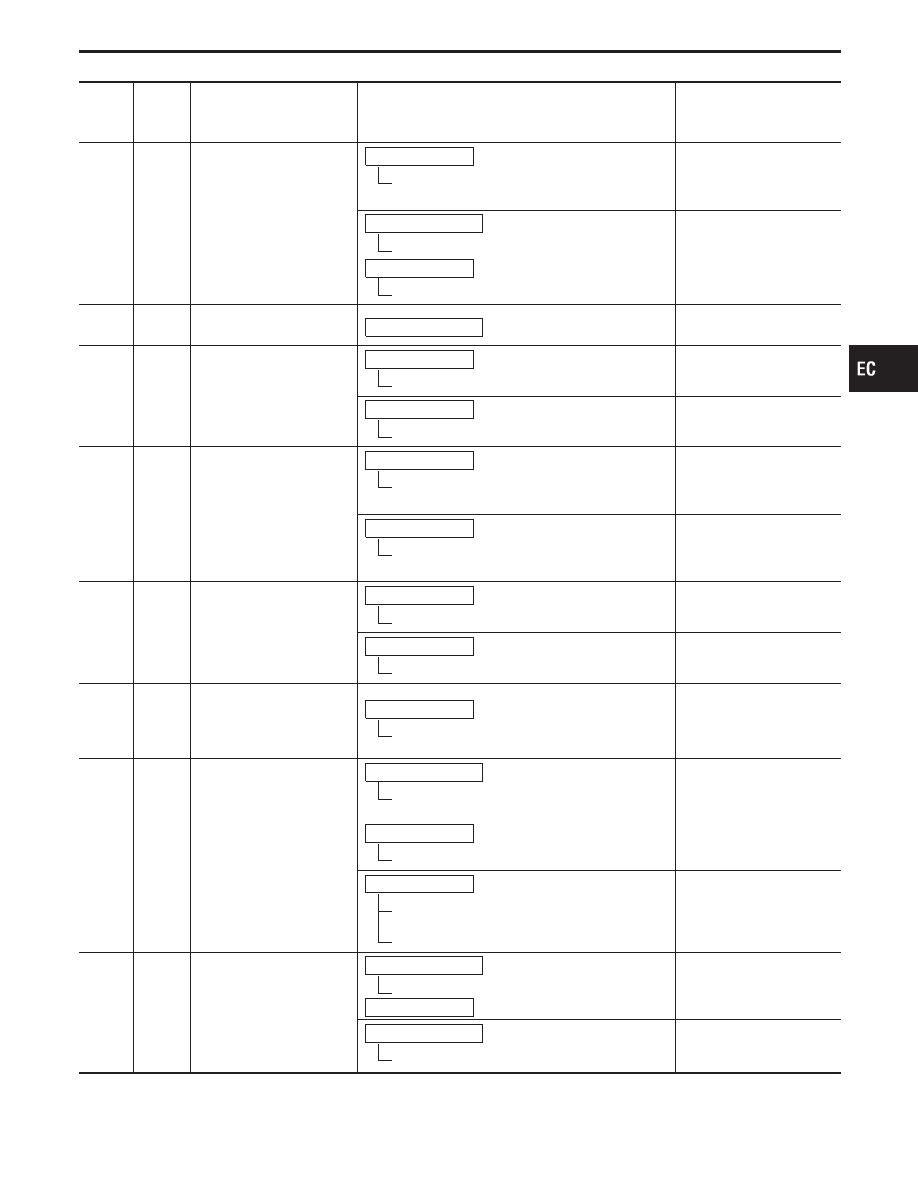
Ignition signal (No. 1)
Ignition signal (No. 8)
Ignition signal (No. 7)
Ignition signal (No. 3)
Ignition signal (No. 6)
Ignition signal (No. 5)
Ignition signal (No. 4)
Ignition signal (No. 2)
Engine is running.
Idle speed
Approximately 0.38V
SEF538T
Engine is running.
Engine speed is 2,000 rpm.
Approximately 0.55V
SEF539T
45
LG/B
Vacuum cut valve bypass
valve
Ignition switch “ON”
BATTERY VOLTAGE
(11 - 14V)
48
PU/W
Malfunction indicator lamp
Ignition switch “ON”
Approximately 0.1V
Engine is running.
Idle speed
BATTERY VOLTAGE
(11 - 14V)
49
B/R
Air conditioner relay
Engine is running.
Both air conditioner switch and blower switch
are “ON”.
0 - 1V
Engine is running.
Air conditioner switch is “OFF”.
BATTERY VOLTAGE
(11 - 14V)
52
W/G
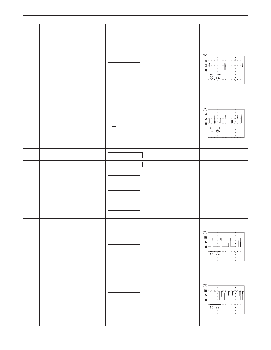
Tachometer
Engine is running.
Idle speed
Approximately 7V
SEF540T
Engine is running. (Warmed-up condition)
Engine speed is 2,000 rpm.
Approximately 0 - 14V
SEF541T
TROUBLE DIAGNOSIS — General Description
ECM Terminals and Reference Value (Cont’d)
EC-110
TER-
MINAL
NO.
WIRE
COLOR
ITEM
CONDITION
DATA
(DC voltage)
55
58
P
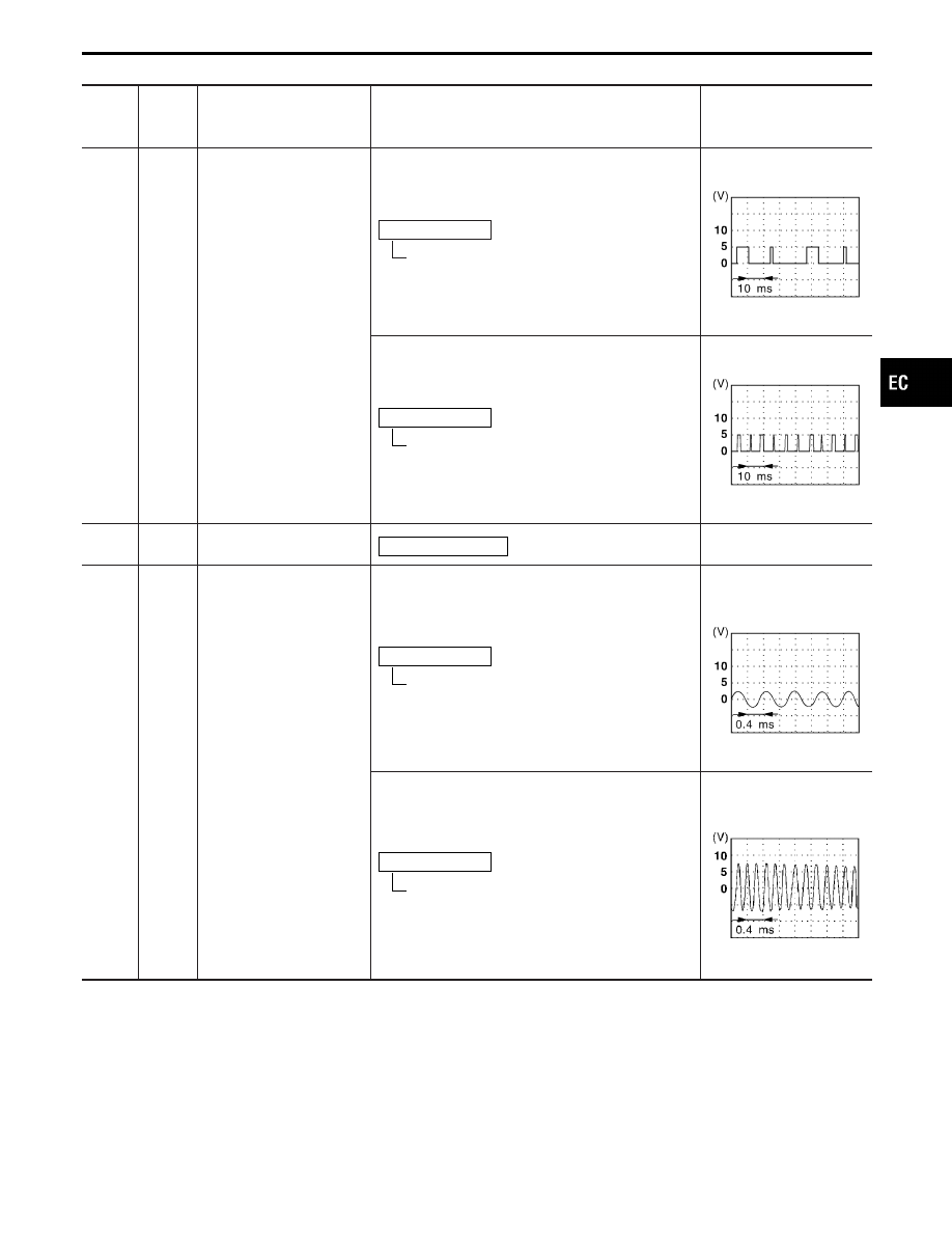
Crankshaft position sen-
sor (REF)
Engine is running. (Warmed-up condition)
Idle speed
Approximately 0.6 - 1.0V
SEF389X
Engine is running. (Warmed-up condition)
Engine speed is 2,000 rpm.
Approximately 0.8 - 0.9V
SEF390X
56
W/L
Power supply (Back-up)
Ignition switch “OFF”
BATTERY VOLTAGE
(11 - 14V)
57
B/R
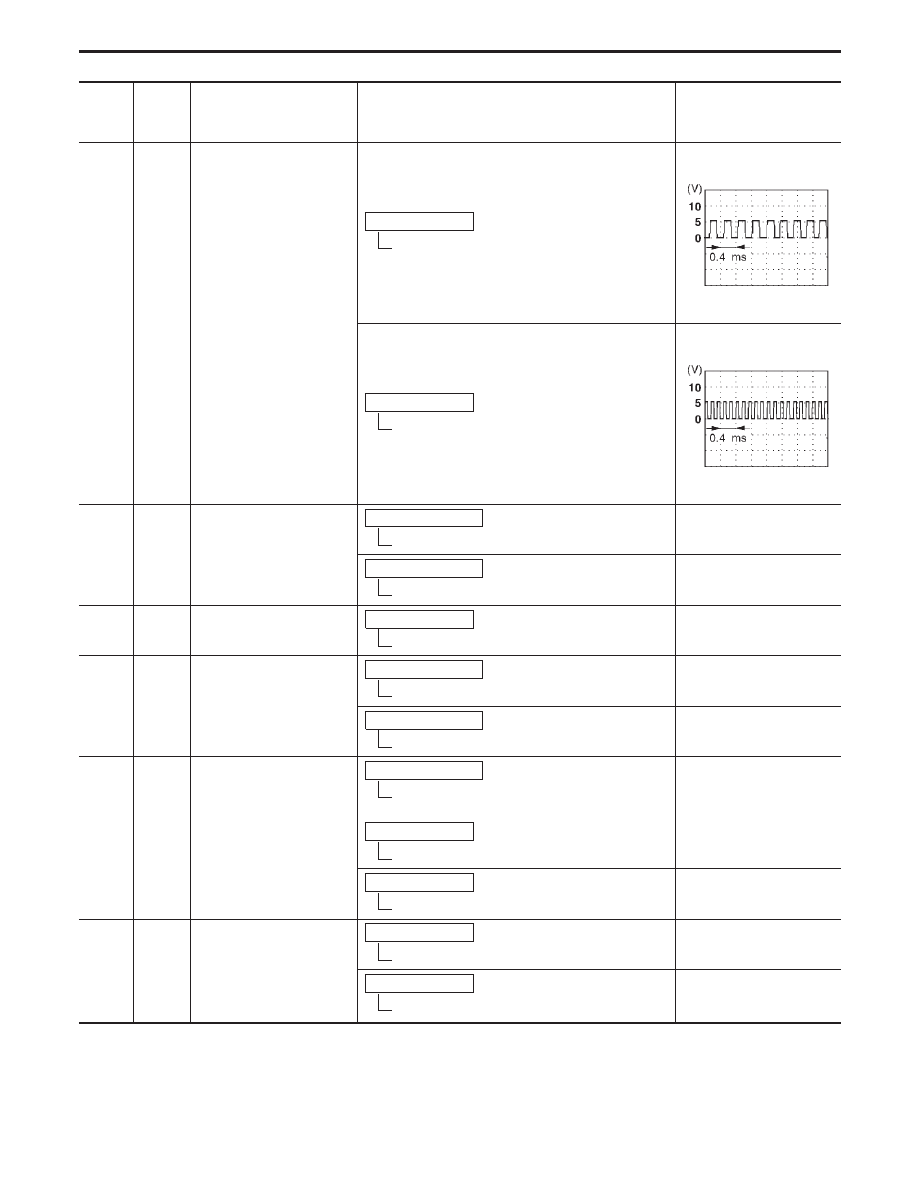
Crankshaft position sen-
sor (OBD)
Engine is running. (Warmed-up condition)
Idle speed
Approximately 1.7V
(AC voltage)
SEF391X
Engine is running. (Warmed-up condition)
Engine speed is 2,000 rpm.
Approximately 0V
(
—
)
SEF546T
GI
MA
EM
LC
FE
AT
PD
FA
RA
BR
ST
RS
BT
HA
EL
IDX
TROUBLE DIAGNOSIS — General Description
ECM Terminals and Reference Value (Cont’d)
EC-111
TER-
MINAL
NO.
WIRE
COLOR
ITEM
CONDITION
DATA
(DC voltage)
59
L
Camshaft position sensor
(POS)
Engine is running. (Warmed-up condition)
Idle speed
Approximately 2.5V
SEF547T
Engine is running. (Warmed-up condition)
Engine speed is 2,000 rpm.
Approximately 2.4V
SEF548T
61
L/W
Throttle position sensor
signal
Ignition switch “ON” (Warmed-up condition)*
Accelerator pedal released
Approximately 0.5V
Ignition switch “ON” (Warmed-up condition)*
Accelerator pedal fully depressed
Approximately 4.2V
62
B
Mass air flow sensor
ground
Engine is running. (Warmed-up condition)
Idle speed
Approximately 0V
63
G
Throttle position sensor
Ignition switch “ON” (Warmed-up condition)*
Accelerator pedal fully released
0.15 - 0.85V
Ignition switch “ON” (Warmed-up condition)
Accelerator pedal fully depressed
3.5 - 4.7V
64
W
Absolute pressure sensor
Ignition switch “ON”
For 5 seconds after turning ignition switch
“ON”
Engine is running.
For 5 seconds after starting engine
Approximately 4.4V
Engine is running. (Warmed-up condition)
More than 5 seconds after starting engine
Approximately 1.2V
65
W
Mass air flow sensor
Engine is running. (Warmed-up condition)
Idle speed
1.0 - 1.4V
Engine is running. (Warmed-up condition)
Engine speed is 2,500 rpm.
Approximately 2.1V
*: More than −40.0 kPa (−300 mmHg, −11.81 inHg) of vacuum is applied to the throttle opener with a handy vacuum pump.
TROUBLE DIAGNOSIS — General Description
ECM Terminals and Reference Value (Cont’d)
EC-112
Нет комментариевНе стесняйтесь поделиться с нами вашим ценным мнением.
Текст