Infiniti Q45 (FY33). Manual — part 93
SBR371E
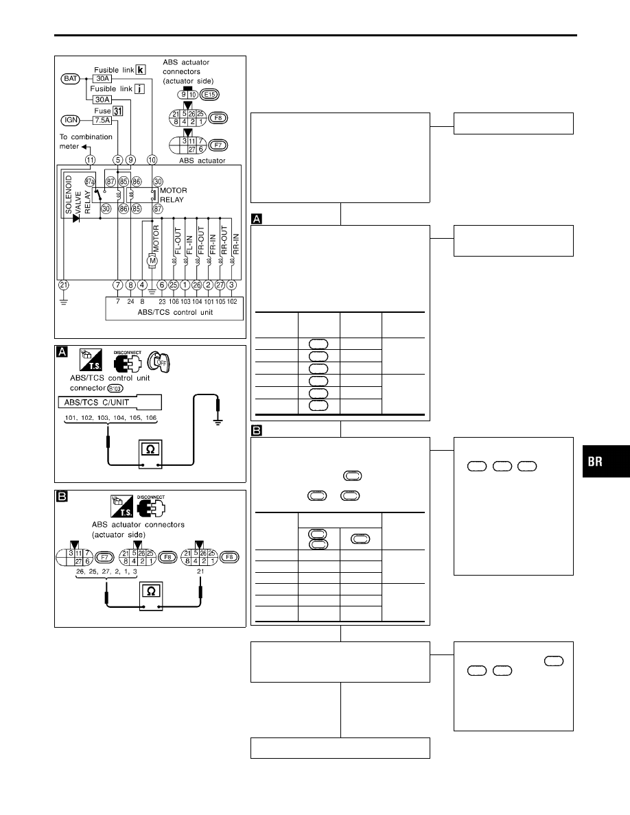
Diagnostic Procedure 8 (ABS actuator solenoid
valve)
Code No. 41, 45, 55, 42, 46, 56 of ABS/TCS control unit
SBR372E
SBR373E
1. Disconnect connectors from ABS/TCS
control unit, ABS actuator and ABS
relay unit. Check terminals for damage
or loose connections. Then reconnect
connectors.
2. Carry out self-diagnosis again.
Do ABS/TCS warning lamp and TCS
OFF indicator activate again?
Yes
E
No
Inspection end
ABS ACTUATOR SOLENOID VALVE
CHECK
----------------------------------------------------------------------------------------------------------------------------------------------------------------------------------------------------------------------------------------------------------------------------------------------------------------
1. Disconnect connectors from ABS/TCS
control unit.
2. Check resistance between ABS/TCS
control unit connector terminals and
ground.
NG
E
OK
Go to Diagnostic Proce-
dure 9. (See next page.)
1. Disconnect ABS actuator 8-pin connec-
tor.
2. Check resistance between ABS actua-
tor 8-pin connector
F8
(ABS actuator
side) terminals and ABS actuator 8-pin
connector
F7
or
F8
(ABS actuator
side) terminal.
NG
E
OK
Check the following.
I
Harness connectors
B103
,
F8
,
F7
I
Harness for open or
short between ABS
actuator connector and
ABS/TCS control unit
connector
I
Harness for open or
short between ABS
actuator and ground
If NG, repair harness or
connectors.
Check resistance between solenoid valve
terminals
q
1
,
q
25
,
q
2
,
q
26
,
q
3
,
q
27
.
Resistance: 8.1 - 16.0
Ω
NG
E
OK
Check the following.
I
Harness connector
F7
,
E15
,
F8
I
Harness for open or
short between actuator
connector terminals
If NG, repair harness or
connectors.
Replace actuator.
Code No.
Control
unit
Ground
Resis-
tance
41
104
—
2.9 - 6.0
Ω
45
106
—
55
105
—
42
101
—
5.2 -
10.0
Ω
46
103
—
56
102
—
Code No.
ABS actuator
Resis-
tance
F7
,
F8
F8
41
q
26
q
21
2.9 - 6.0
Ω
45
q
25
q
21
55
q
27
q
21
42
q
2
q
21
5.2 -
10.0
Ω
46
q
1
q
21
56
q
3
q
21
GI
MA
EM
LC
EC
FE
AT
PD
FA
RA
ST
RS
BT
HA
EL
IDX
TROUBLE DIAGNOSES FOR SELF-DIAGNOSTIC ITEMS
H
H
H
H
BR-89
SBR371E
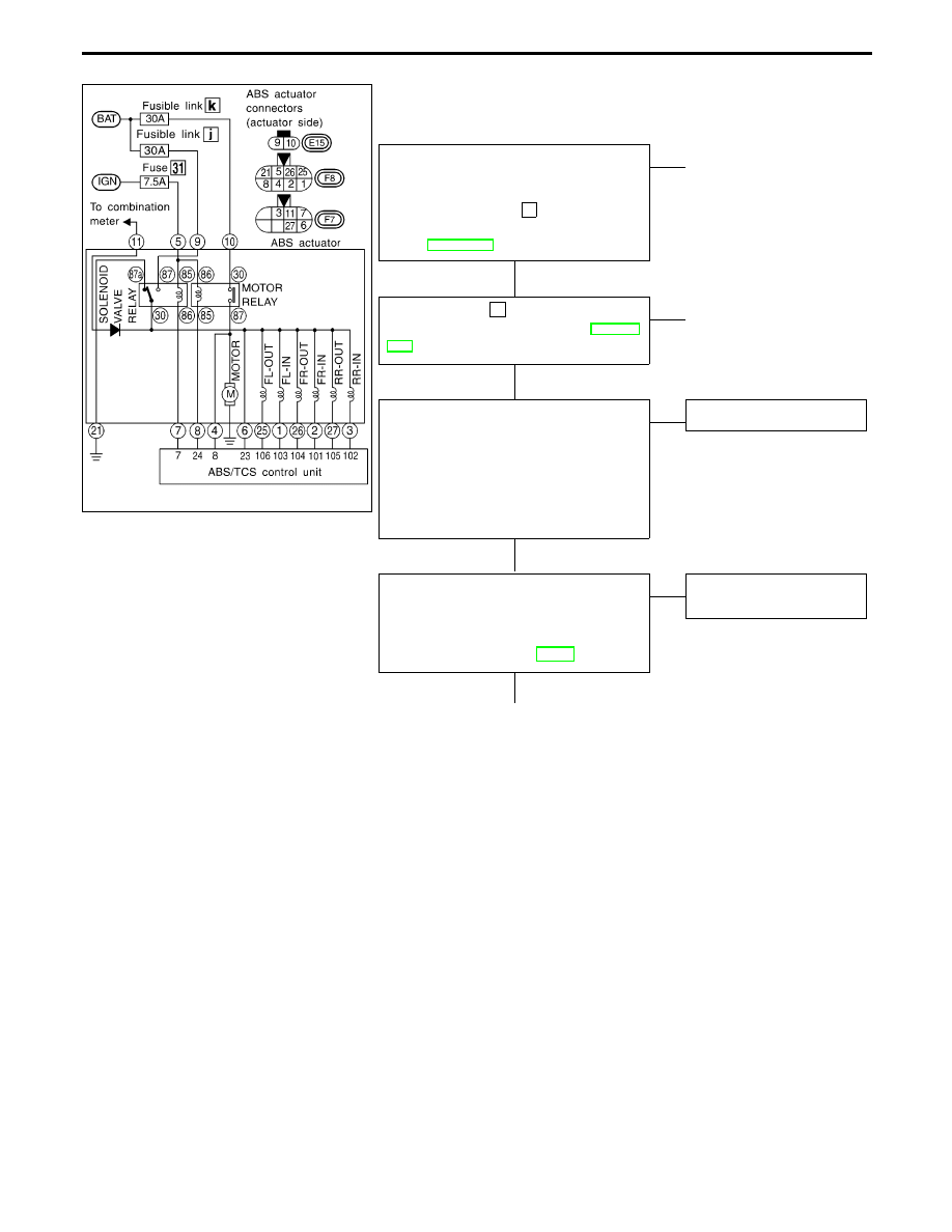
Diagnostic Procedure 9 (Solenoid valve relay)
Code No. 63 of ABS/TCS control unit
SOLENOID VALVE POWER SUPPLY
CHECK
----------------------------------------------------------------------------------------------------------------------------------------------------------------------------------------------------------------------------------------------------------------------------------------------------------------
Check 30A fusible link j . For fusible link
layout, refer to POWER SUPPLY ROUT-
ING in EL section.
OK
E
NG
q
A
(Skip page.)
Check 7.5A fuse
31
. For fuse layout, refer
to POWER SUPPLY ROUTING in EL sec-
tion.
OK
E
NG
q
B
(Skip page.)
1. Disconnect connectors from ABS/TCS
control unit and ABS actuator. Check
terminals for damage or loose connec-
tion. Then reconnect connectors.
2. Carry out self-diagnosis again.
Do ABS warning lamp and TCS OFF
indicator activate again?
Yes
E
No
Inspection end
GROUND CIRCUIT CHECK
----------------------------------------------------------------------------------------------------------------------------------------------------------------------------------------------------------------------------------------------------------------------------------------------------------------
Refer to ABS/TCS CONTROL UNIT
GROUND and ABS ACTUATOR GROUND
in Ground Circuit Check, BR-79.
OK
E
NG
Repair harness and con-
nectors.
q
C
TROUBLE DIAGNOSES FOR SELF-DIAGNOSTIC ITEMS
H
H
H
H
BR-90
SBR375E
SBR374E
SBR376E
q
C
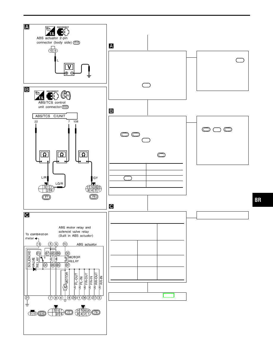
SOLENOID VALVE POWER SUPPLY
CHECK
----------------------------------------------------------------------------------------------------------------------------------------------------------------------------------------------------------------------------------------------------------------------------------------------------------------
1. Disconnect connectors from ABS actua-
tor.
2. Check voltage between ABS actuator
2-pin connector
E15
(body side) termi-
nal
q
9
and ground.
Battery voltage should exist.
OK
E
NG
Check the following.
I
Harness connector
E15
I
Harness for open or
short between ABS
actuator and fuse
If NG, repair harness or
connectors.
CIRCUIT CHECK
----------------------------------------------------------------------------------------------------------------------------------------------------------------------------------------------------------------------------------------------------------------------------------------------------------------
1. Disconnect ABS actuator 8-pin connec-
tor
F7
,
F8
and ABS/TCS control
unit connectors
B103
.
2. Check continuity between ABS/TCS con-
trol unit connector terminals and ABS
actuator 8-pin connector
F7
(body
side) terminals.
Continuity should exist.
OK
E
NG
Check the following.
I
Harness connectors
F7
,
B103
,
F8
I
Harness for open or short
between ABS actuator
terminal (body side) and
ABS/TCS control unit
If NG, repair harness or
connectors.
SOLENOID VALVE RELAY CHECK
----------------------------------------------------------------------------------------------------------------------------------------------------------------------------------------------------------------------------------------------------------------------------------------------------------------
OK
E
NG
Replace ABS actuator.
Go to Diagnostic Procedure 8, BR-89.
Control unit
ABS actuator
q
7
q
7
108
q
5
q
22
q
11
Condition
Continuity exist-
ence between
terminals
q
6
and
q
21
Battery voltage
not applied
between each
terminal
q
5
and
q
7
Yes
Battery voltage
applied between
each terminal
q
5
and
q
7
No
Check resis-
tance between
each terminal
q
5
and
q
7
Approx. 100
Ω
GI
MA
EM
LC
EC
FE
AT
PD
FA
RA
ST
RS
BT
HA
EL
IDX
TROUBLE DIAGNOSES FOR SELF-DIAGNOSTIC ITEMS
Diagnostic Procedure 9 (Solenoid valve relay)
(Cont’d)
H
H
H
H
BR-91
SBR377E
SBR378E
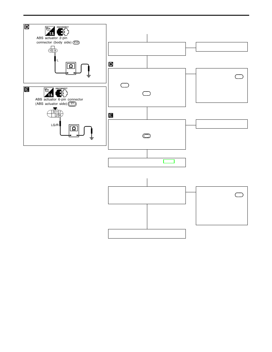
q
A
Replace fusible link.
Does the fusible link blow out?
Yes
E
No
Inspection end
RELAY POWER SUPPLY CIRCUIT
----------------------------------------------------------------------------------------------------------------------------------------------------------------------------------------------------------------------------------------------------------------------------------------------------------------
1. Disconnect ABS actuator 2-pin connec-
tor
E15
.
2. Check continuity between ABS actuator
2-pin connector
E15
(body side) termi-
nal
q
9
and ground.
Continuity should not exist.
OK
E
NG
Check the following.
I
Harness connector
E15
I
Harness for open or
short between ABS
actuator and fuse
If NG, repair harness or
connectors.
1. Disconnect ABS actuator connectors
and control unit connector.
2. Check continuity between ABS actuator
6-pin connector
F7
(ABS actuator
side) terminal
q
6
and ground.
Continuity should exist.
OK
E
NG
Replace ABS actuator.
Go to Diagnostic Procedure 8, BR-89.
q
B
Replace fuse.
Does the fuse blow out when ignition
switch is turned “ON”?
No
E
Yes
Check the following.
I
Harness connector
F8
I
Harness for open or
short between ABS
actuator connector and
fuse
If NG, repair harness or
connectors.
Inspection end
TROUBLE DIAGNOSES FOR SELF-DIAGNOSTIC ITEMS
Diagnostic Procedure 9 (Solenoid valve relay)
(Cont’d)
H
H
H
H
H
H
BR-92
Нет комментариевНе стесняйтесь поделиться с нами вашим ценным мнением.
Текст