Infiniti Q45 (FY33). Manual — part 27
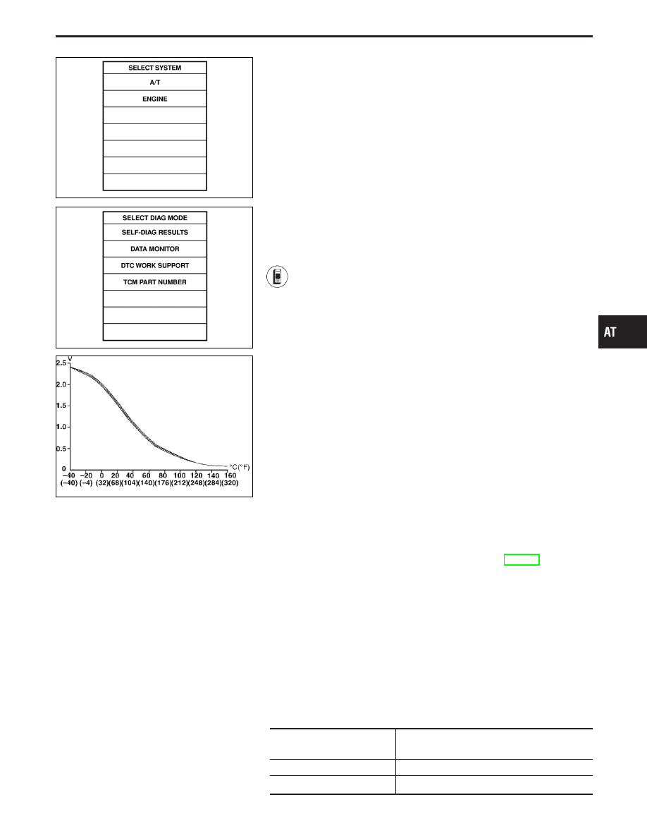
SAT014K
SAT971J
SAT021J
DIAGNOSTIC TROUBLE CODE (DTC) CONFIRMA-
TION PROCEDURE
CAUTION:
I
Always drive vehicle at a safe speed.
I
Be careful not to rev engine into the red zone on the
tachometer.
NOTE:
If “DIAGNOSTIC TROUBLE CODE CONFIRMATION PROCE-
DURE” has been previously conducted, always turn ignition
switch “OFF” and wait at least 5 seconds before conducting
the next test.
TESTING CONDITION:
Always drive vehicle on a level road to improve the accuracy
of test.
After the repair, perform the following procedure to confirm the
malfunction is eliminated.
1)
Start engine and select “DATA MONITOR” mode for
“A/T” with CONSULT-II.
2)
Make sure that output voltage of A/T fluid temperature
sensor is within the range below.
FLUID TEMP SEN: 0.4 - 1.5V
If out of range, drive the vehicle to decrease the voltage
(warm up the fluid) or stop engine to increase the volt-
age (cool down the fluid).
3)
Select “3RD GR FNCTN P0733” of “DTC WORK SUP-
PORT” mode for “A/T” with CONSULT-II and touch
“START”.
4)
Accelerate vehicle to 82 to 97 km/h (51 to 60 MPH)
under the following condition and release the accelera-
tor pedal completely.
THROTTLE POSI: Less than 1.0/8 (at all times during
step 4)
Selector lever: D position (OD “ON”)
I
Check that “GEAR” shows “4” after releasing pedal.
5)
Depress accelerator pedal steadily with 3.5/8 - 4.5/8 of
“THROTTLE POSI” from a speed of 82 to 97 km/h (51
to 60 MPH) until “TESTING” changes to “STOP
VEHICLE” or “COMPLETED”. (It will take approximately
3 seconds.)
If the check result NG appears on CONSULT-II screen,
go to “DIAGNOSTIC PROCEDURE”, AT-107.
If “STOP VEHICLE” appears on CONSULT-II screen, go
to following step.
I
Check that “GEAR” shows “3” when depressing
accelerator pedal with 3.5/8 - 4.5/8 of “THROTTLE
POSI”.
I
If “TESTING” does not appear on CONSULT-II for a
long
time,
select
“SELF-DIAG
RESULTS”
for
“ENGINE”. In case a 1st trip DTC other than P0733
is shown, refer to applicable “TROUBLE DIAGNOSIS
FOR DTC”.
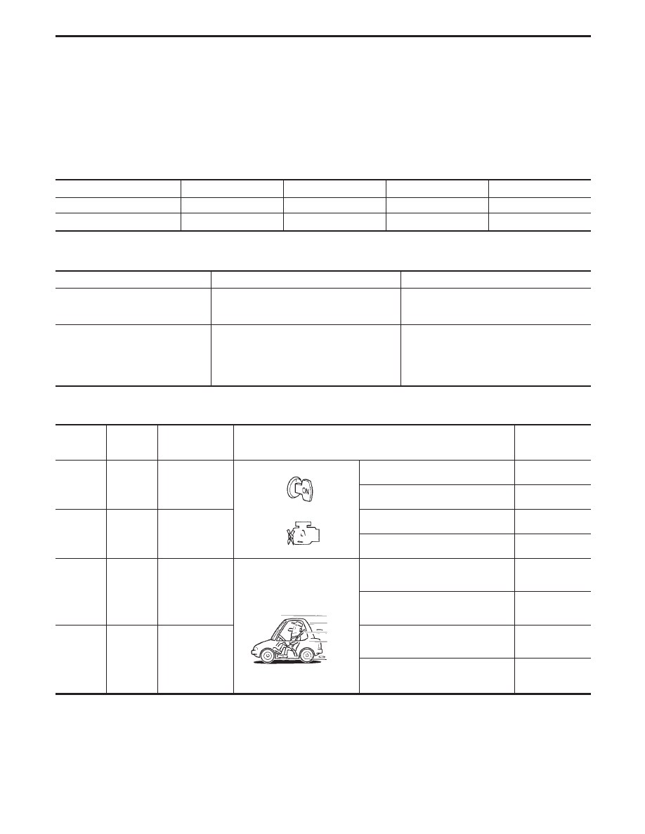
6)
Stop vehicle.
7)
Follow the instruction displayed. (Check for normal shift-
ing referring to the table below.)
Vehicle condition
Gear on actual transmission shift pattern when
screen is changed to 1
,
2
,
3
,
4
No malfunction exists.
1
,
2
,
3
,
4
Malfunction for P0733 exists.
1
,
1
,
4
,
4
GI
MA
EM
LC
EC
FE
PD
FA
RA
BR
ST
RS
BT
HA
EL
IDX
TROUBLE DIAGNOSIS FOR DTC P0733
A/T 3rd Gear Function (Cont’d)
AT-105

8)
Make sure that “OK” is displayed. (If “NG” is displayed,
refer to “DIAGNOSTIC PROCEDURE”.)
Refer to “DIAGNOSTIC PROCEDURE”, AT-107.
Refer to shift schedule, AT-276.
------------------------------------------------------------------------------------------------------------------------------------------------------------------------------------------------------------------------------------------------------ OR ------------------------------------------------------------------------------------------------------------------------------------------------------------------------------------------------------------------------------------------------------
Follow the procedure “With CONSULT-II”.
TROUBLE DIAGNOSIS FOR DTC P0733
A/T 3rd Gear Function (Cont’d)
AT-106
SAT536I
SAT367H
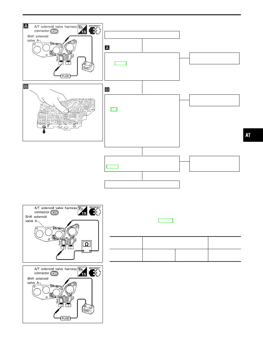
DIAGNOSTIC PROCEDURE
INSPECTION START
CHECK SHIFT SOLENOID VALVE.
1. Remove control valve assembly. Refer
to AT-195.
2. Check shift solenoid valve operation.
I
Shift solenoid valve A
Refer to “Component Inspection” below.
OK
E
NG
Repair or replace shift sole-
noid valve assembly.
CHECK CONTROL VALVE.
1. Disassemble control valve assembly.
Refer to “Control Valve Assembly”, AT-
221.
2. Check to ensure that:
I
Valve, sleeve and plug slide along
valve bore under their own weight.
I
Valve, sleeve and plug are free from
burrs, dents and scratches.
I
Control valve springs are free from
damage, deformation and fatigue.
I
Hydraulic line is free from obstacles.
OK
E
NG
Repair control valve assem-
bly.
Perform DIAGNOSTIC TROUBLE CODE
(DTC) CONFIRMATION PROCEDURE,
AT-105.
OK
E
NG
Check control valve again.
Repair or replace control
valve assembly.
INSPECTION END
SAT537I
COMPONENT INSPECTION
Shift solenoid valve A
I
For removal, refer to AT-195.
Resistance check
I
Check resistance between two terminals.
Solenoid valve
Terminal No.
Resistance
(Approx.)
Shift solenoid
valve A
q
3
Ground
20 - 40
Ω
SAT536I
Operation check
I
Check solenoid valve by listening for its operating sound while
applying battery voltage to the terminal and ground.
GI
MA
EM
LC
EC
FE
PD
FA
RA
BR
ST
RS
BT
HA
EL
IDX
TROUBLE DIAGNOSIS FOR DTC P0733
A/T 3rd Gear Function (Cont’d)
H
H
H
H
AT-107
A/T 4th Gear Function
DESCRIPTION
I
This is an OBD-II self-diagnostic item and not available in TCM self-diagnosis.
I
This malfunction will not be detected while the O/D OFF indicator lamp is indicating another self-diagno-
sis malfunction.
I
This malfunction is detected when the A/T does not shift into fourth gear position or the torque converter
clutch does not lock up as instructed by the TCM. This is not caused by electrical malfunction (circuits open
or shorted) but by mechanical malfunction such as control valve sticking, improper solenoid valve
operation, malfunctioning oil pump or torque converter clutch, etc.
Gear position
1
2
3
4
Shift solenoid valve A
ON (Closed)
OFF (Open)
OFF (Open)
ON (Closed)
Shift solenoid valve B
ON (Closed)
ON (Closed)
OFF (Open)
OFF (Open)
CONSULT-II REFERENCE VALUE IN DATA MONITOR MODE
Remarks: Specification data are reference values.
Monitor item
Condition
Specification
Torque converter clutch solenoid
valve duty
Lock-up “OFF”
"
Lock-up “ON”
Approximately 4%
"
Approximately 94%
Line pressure solenoid valve duty
Small throttle opening
(Low line pressure)
"
Large throttle opening
(High line pressure)
Approximately 29%
"
Approximately 95%
TCM TERMINALS AND REFERENCE VALUE
Remarks: Specification data are reference values.
Terminal
No.
Wire color
Item
Condition
Judgement
standard
(Approx.)
1
G/R
Line pressure
solenoid valve
When releasing accelerator pedal
after warming up engine.
1.5 - 2.5V
When depressing accelerator pedal
fully after warming up engine.
0V
2
W/B
Line pressure
solenoid valve
(with dropping
resistor)
When releasing accelerator pedal
after warming up engine.
5 - 14V
When depressing accelerator pedal
fully after warming up engine.
0V
6
R/Y
Shift solenoid
valve A
When shift solenoid valve A oper-
ates.
(When driving in “D
1
” or “D
4
”.)
Battery voltage
When shift solenoid valve A does not
operate.
(When driving in “D
2
” or “D
3
”.)
0V
7
LG/B
Shift solenoid
valve B
When shift solenoid valve B oper-
ates.
(When driving in “D
1
” or “D
2
”.)
Battery voltage
When shift solenoid valve B does
not operate.
(When driving in “D
3
” or “D
4
”.)
0V
TROUBLE DIAGNOSIS FOR DTC P0734
AT-108
Нет комментариевНе стесняйтесь поделиться с нами вашим ценным мнением.
Текст