Infiniti Q45 (FY33). Manual — part 25

5)
Depress accelerator pedal to WOT (more than 7.0/8 of
“THROTTLE POSI”) quickly from a speed of 20 to 25
km/h (12 to 16 MPH) until “TESTING” changes to “STOP
VEHICLE” or “COMPLETED”. (It will take approximately
3 seconds.)
If the check result NG appears on CONSULT-II screen,
go to “DIAGNOSTIC PROCEDURE”, AT-98.
If “STOP VEHICLE” appears on CONSULT-II screen, go
to the following step.
I
Check that “GEAR” shows “1” when depressing
accelerator pedal to WOT.
I
If “TESTING” does not appear on CONSULT-II for a
long
time,
select
“SELF-DIAG
RESULTS”
for
“ENGINE”. In case a 1st trip DTC other than P0731
is shown, refer to applicable “TROUBLE DIAGNOSIS
FOR DTC”.
6)
Stop vehicle.
7)
Follow the instruction displayed. (Check for normal shift-
ing referring to the table below.)
Vehicle condition
Gear on actual transmission shift pattern when
screen is changed to 1
,
2
,
3
,
4
No malfunction exists
1
,
2
,
3
,
4
Malfunction for P0731 exists.
2
,
2
,
3
,
3
4
,
3
,
3
,
4
8)
Make sure that “OK” is displayed. (If “NG” is displayed,
refer to “DIAGNOSTIC PROCEDURE”.)
Refer to “DIAGNOSTIC PROCEDURE”, AT-98.
Refer to shift schedule, AT-276.
------------------------------------------------------------------------------------------------------------------------------------------------------------------------------------------------------------------------------------------------------ OR ------------------------------------------------------------------------------------------------------------------------------------------------------------------------------------------------------------------------------------------------------
Follow the procedure “With CONSULT-II”.
GI
MA
EM
LC
EC
FE
PD
FA
RA
BR
ST
RS
BT
HA
EL
IDX
TROUBLE DIAGNOSIS FOR DTC P0731
A/T 1st Gear Function (Cont’d)
AT-97
SAT532I
SAT367H
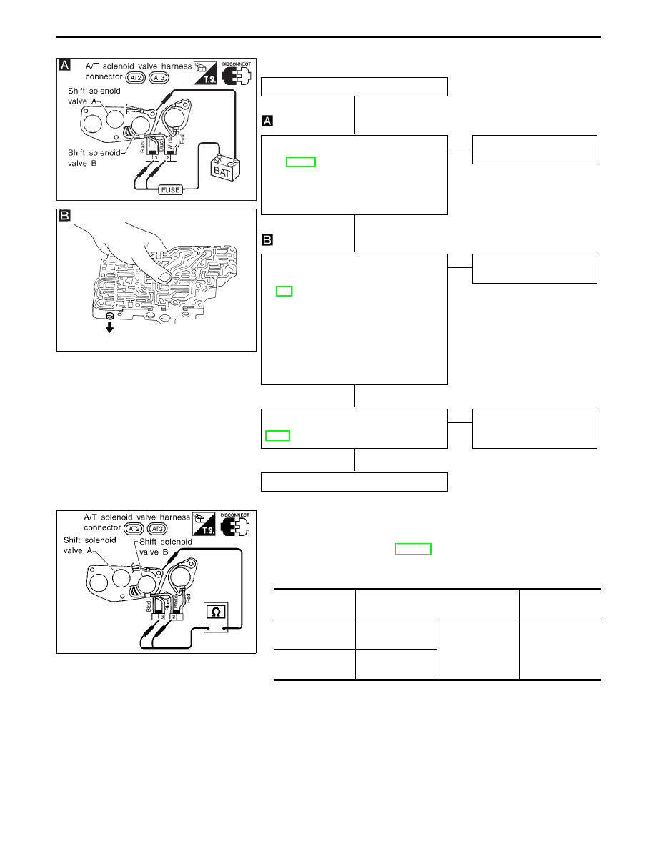
DIAGNOSTIC PROCEDURE
INSPECTION START
CHECK SHIFT SOLENOID VALVE.
1. Remove control valve assembly. Refer
to AT-195.
2. Check shift solenoid valve operation.
I
Shift solenoid valve A
I
Shift solenoid valve B
Refer to “Component Inspection” below.
OK
E
NG
Repair or replace shift sole-
noid valve assembly.
CHECK CONTROL VALVE.
1. Disassemble control valve assembly.
Refer to “Control Valve Assembly”, AT-
221.
2. Check to ensure that:
I
Valve, sleeve and plug slide along
valve bore under their own weight.
I
Valve, sleeve and plug are free from
burrs, dents and scratches.
I
Control valve springs are free from
damage, deformation and fatigue.
I
Hydraulic line is free from obstacles.
OK
E
NG
Repair control valve assem-
bly.
Perform DIAGNOSTIC TROUBLE CODE
(DTC) CONFIRMATION PROCEDURE,
AT-96.
OK
E
NG
Check control valve again.
Repair or replace control
valve assembly.
INSPECTION END
SAT533I
COMPONENT INSPECTION
Shift solenoid valve A and B
I
For removal, refer to AT-195.
Resistance check
I
Check resistance between two terminals.
Solenoid valve
Terminal No.
Resistance
(Approx.)
Shift solenoid
valve A
q
3
Ground
20 - 40
Ω
Shift solenoid
valve B
q
2
TROUBLE DIAGNOSIS FOR DTC P0731
A/T 1st Gear Function (Cont’d)
H
H
H
H
AT-98
SAT532I
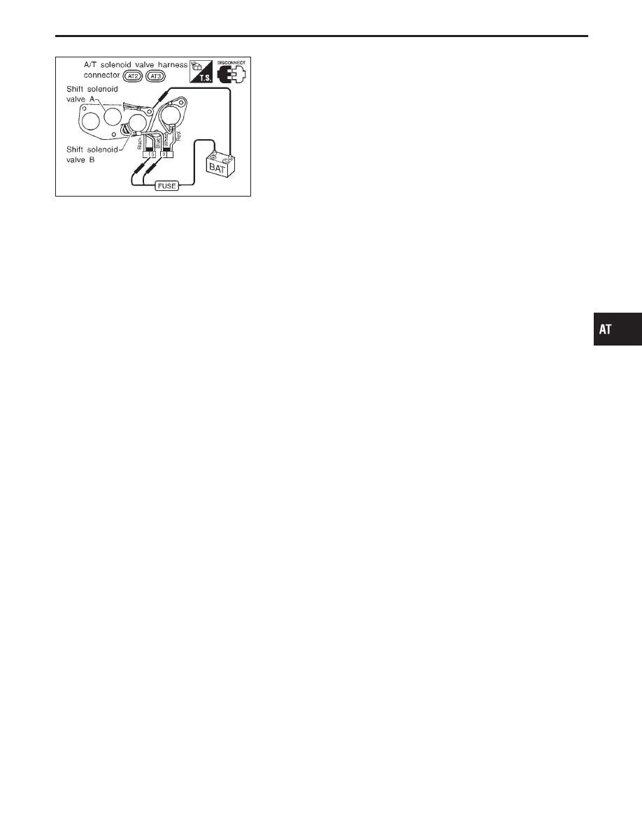
Operation check
I
Check solenoid valve by listening for its operating sound while
applying battery voltage to the terminal and ground.
GI
MA
EM
LC
EC
FE
PD
FA
RA
BR
ST
RS
BT
HA
EL
IDX
TROUBLE DIAGNOSIS FOR DTC P0731
A/T 1st Gear Function (Cont’d)
AT-99
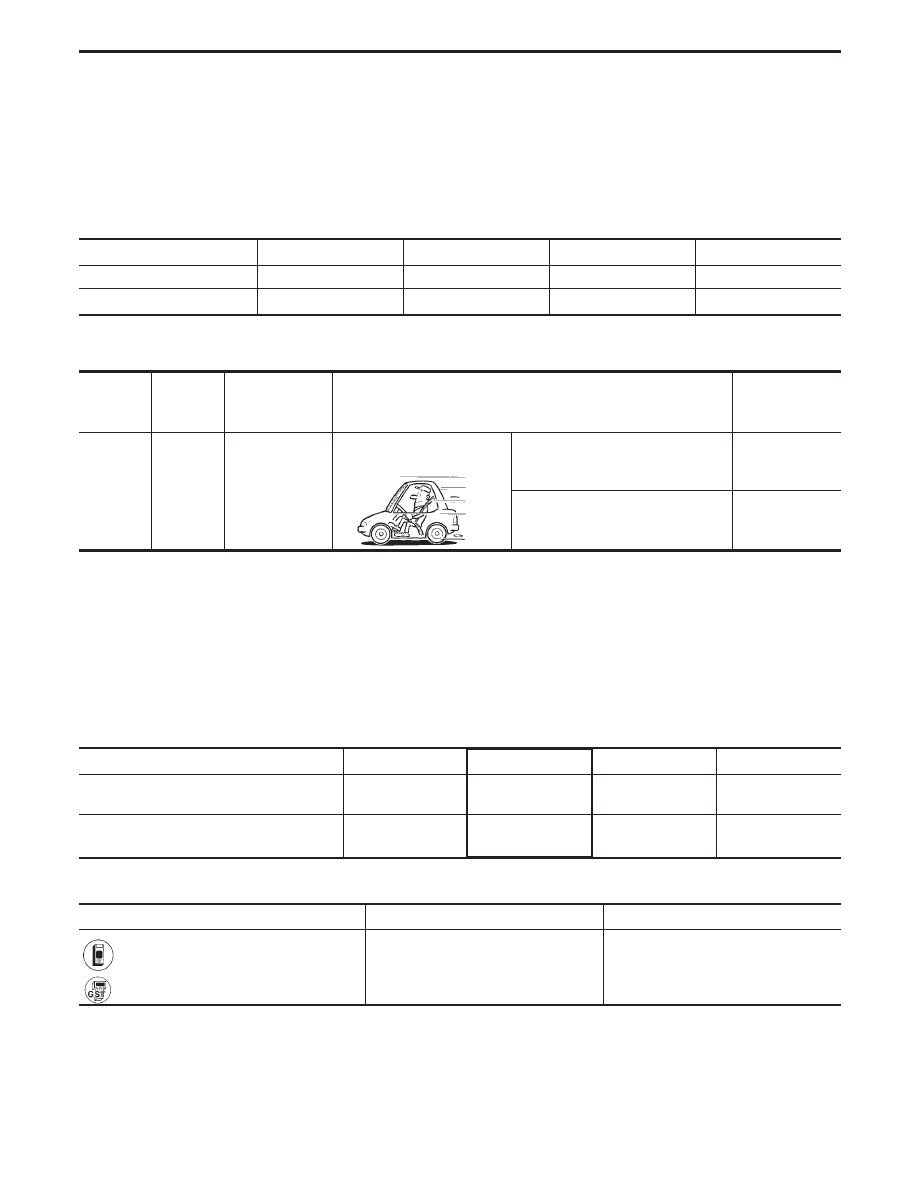
A/T 2nd Gear Function
DESCRIPTION
I
This is an OBD-II self-diagnostic item and not available in TCM self-diagnosis.
I
This malfunction will not be detected while the O/D OFF indicator lamp is indicating another self-diagno-
sis malfunction.
I
This malfunction is detected when the A/T does not shift into second gear position as instructed by the
TCM. This is not caused by electrical malfunction (circuits open or shorted) but by mechanical malfunc-
tion such as control valve sticking, improper solenoid valve operation, etc.
Gear position
1
2
3
4
Shift solenoid valve A
ON (Closed)
OFF (Open)
OFF (Open)
ON (Closed)
Shift solenoid valve B
ON (Closed)
ON (Closed)
OFF (Open)
OFF (Open)
TCM TERMINALS AND REFERENCE VALUE
Remarks: Specification data are reference values.
Terminal
No.
Wire color
Item
Condition
Judgement
standard
(Approx.)
7
LG/B
Shift solenoid
valve B
When shift solenoid valve B oper-
ates.
(When driving in “D
1
” or “D
2
”.)
Battery voltage
When shift solenoid valve B does
not operate.
(When driving in “D
3
” or “D
4
”.)
0V
ON BOARD DIAGNOSTIC LOGIC
This diagnosis monitors actual gear position by checking the torque converter slip ratio calculated by TCM as
follows:
Torque converter slip ratio = A x C/B
A: Output shaft revolution signal from revolution sensor
B: Engine speed signal from ECM
C: Gear ratio determined as gear position which TCM supposes
If the actual gear position is higher than the position (2nd) supposed by TCM, the slip ratio will be more than
normal. In case the ratio exceeds the specified value, TCM judges this diagnosis malfunction.
This malfunction will be caused when shift solenoid valve B is stuck open.
Gear position supposed by TCM
1
2
3
4
In case of gear position with no malfunc-
tions
1
2
3
4
In case of gear position with shift solenoid
valve B stuck open
4
q
3
3
4
q
: P0732 is detected.
Diagnostic trouble code
Malfunction is detected when ...
Check item (Possible cause)
: A/T 2ND GR FNCTN
A/T cannot be shifted to the 2nd gear
position even if electrical circuit is good.
I
Shift solenoid valve B
I
Each clutch
I
Hydraulic control circuit
: P0732
TROUBLE DIAGNOSIS FOR DTC P0732
AT-100
Нет комментариевНе стесняйтесь поделиться с нами вашим ценным мнением.
Текст