Infiniti Q45 (FY33). Manual — part 423
SEM569B
3.
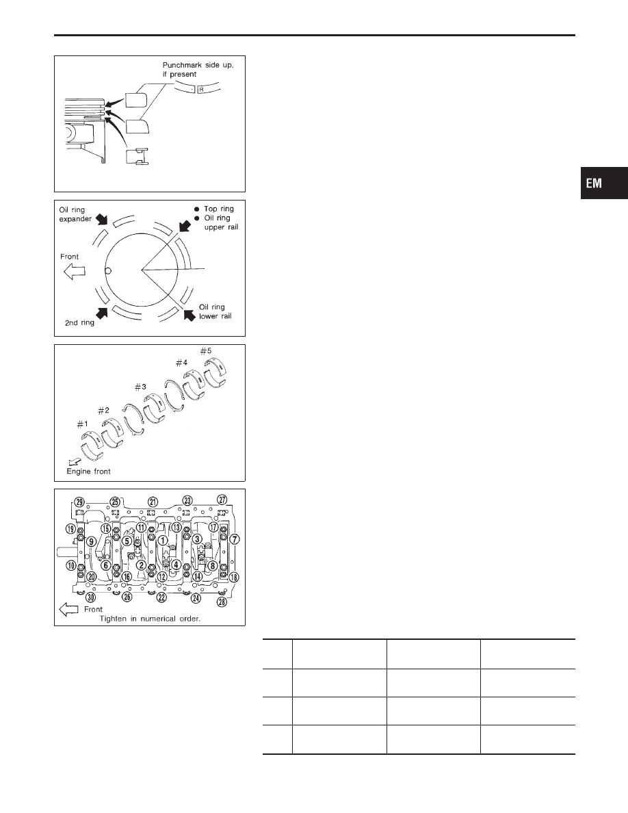
Set piston rings as shown.
CAUTION:
I
When piston rings are not replaced, make sure that piston
rings are mounted in their original positions.
I
When replacing piston rings, these without punchmarks,
present, piston rings can be mounted with either side up.
SEM536E
I
Align piston rings so that end gaps are positioned as
shown in the figure.
SEM753C
CRANKSHAFT
1.
Set main bearings in their proper positions on cylinder block
and main bearing cap.
I
Confirm that correct main bearings are used. Refer to
“Inspection” of this section.
I
Apply engine oil to bearing surface.
SEM461F
2.
Install crankshaft, main bearing caps and beam and tighten
bolts to the specified torque.
I
Lubricate threads and seat surfaces of the bolts with new
engine oil.
I
Prior to tightening bearing cap bolts, place bearing cap in
its proper position by shifting in the axial direction.
I
Tightening procedure
1)
Tighten bolts (
q
1
-
q
20
) to
q
a
.
2)
Turn bolts (
q
1
-
q
20
)
q
b
degrees clockwise with angle
wrench.
3)
Tighten all bolts (
q
21
-
q
30
) to
q
c
.
Unit: N
⋅
m (kg-m, ft-lb)
Bolts
(
q
1
-
q
10
)
Bolts
(
q
11
-
q
20
)
Bolts
(
q
21
-
q
30
)
q
a
36 - 42
(3.7 - 4.3, 27 - 31)
26 - 32
(2.7 - 3.3, 20 - 24)
—
q
b
40
+5
-0
degrees
35
+5
-0
degrees
—
q
c
—
—
46 - 52
(4.7 - 5.3, 34 - 38)
GI
MA
LC
EC
FE
AT
PD
FA
RA
BR
ST
RS
BT
HA
EL
IDX
CYLINDER BLOCK
Assembly (Cont’d)
EM-53
I
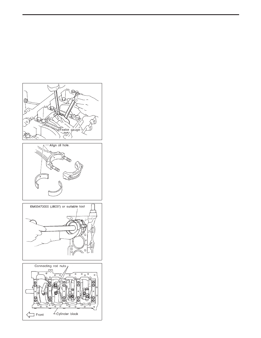
After securing bearing cap bolts, make sure crankshaft
turns smoothly by hand.
SEM462F
3.
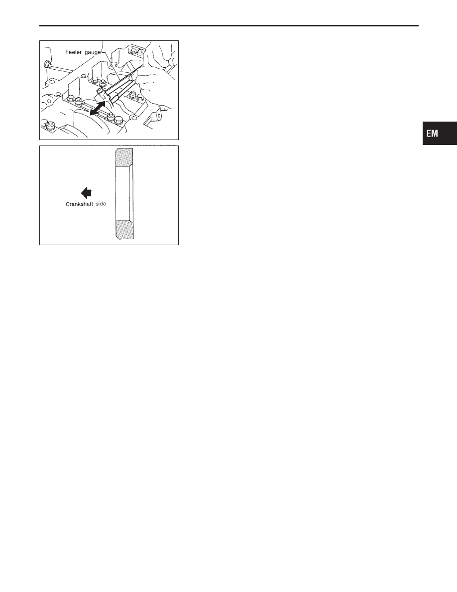
Measure crankshaft end play.
Crankshaft end play:
Standard
0.10 - 0.26 mm (0.0039 - 0.0102 in)
Limit
0.30 mm (0.0118 in)
If beyond the limit, replace bearing with a new one.
SEM159B
4.
Install connecting rod bearings in connecting rods and con-
necting rod caps.
I
Confirm that correct bearings are used. Refer to “Inspec-
tion”.
I
Install bearings so that oil hole in connecting rod aligns
with oil hole of bearing.
SEM460E
5.
Install pistons with connecting rods.
a.
Install them into corresponding cylinders with Tool.
I
Be careful not to scratch cylinder wall with the connecting
rod.
I
Arrange so that front mark on piston head faces toward
front of engine.
I
Apply engine oil to piston rings and sliding surface of
piston.
SEM463F
b.
Install connecting rod caps.
I
Apply engine oil to bolt threads and bearing surface.
Tighten connecting rod bearing cap nuts to the specified
torque.
Tightening procedure:
1) Tighten nuts to 14 to 16 N
⋅
m (1.4 to 1.6 kg-m,
10 to 12 ft-lb).
2) Turn nuts 60 to 65 degrees clockwise with
angle wrench.
CYLINDER BLOCK
Assembly (Cont’d)
EM-54
SEM464F
6.
Measure connecting rod side clearance.
Connecting rod side clearance:
Standard
0.20 - 0.35 mm (0.0079 - 0.0138 in)
Limit
0.40 mm (0.0157 in)
If beyond the limit, replace connecting rod and/or crankshaft.
7.
Install rear oil seal retainer.
SEM537E
REPLACING PILOT CONVERTER
1.
Remove pilot converter.
2.
Install pilot converter.
GI
MA
LC
EC
FE
AT
PD
FA
RA
BR
ST
RS
BT
HA
EL
IDX
CYLINDER BLOCK
Assembly (Cont’d)
EM-55
General Specifications
Cylinder arrangement
V-8
Displacement
cm
3
(cu in)
4,130 (252.01)
Bore and stroke
mm (in)
93 x 76 (3.66 x 2.99)
Valve arrangement
DOHC
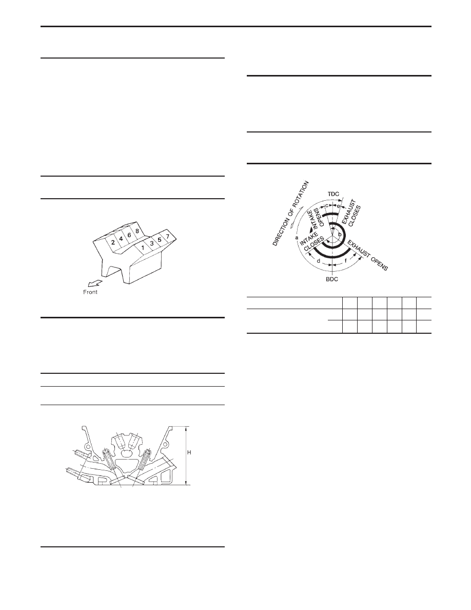
Firing order
1-8-7-3-6-5-4-2
Number of piston rings
Compression
2
Oil
1
Number of main bearings
5
Compression ratio
10.5
Cylinder number
SEM957C
COMPRESSION PRESSURE
Unit: kPa (kg/cm
2
, psi)/300 rpm
Compression pressure
Standard
1,285 (13.1, 186)
Minimum
991 (10.1, 144)
Differential limit between
cylinders
98 (1.0, 14)
Valve timing
EM120
Unit: degree
a
b
c
d
e
f
Intake valve timing control
solenoid valve
ON
232 232
15
37
5
47
OFF 232 232
−5
57
5
47
Inspection and Adjustment
CYLINDER HEAD
Unit: mm (in)
Standard
Limit
Head surface distortion
Less than
0.03 (0.0012)
0.1 (0.004)
SEM956C
Nominal cylinder head height:
H = 130.7 - 130.9 mm (5.146 - 5.154 in)
SERVICE DATA AND SPECIFICATIONS (SDS)
EM-56
Нет комментариевНе стесняйтесь поделиться с нами вашим ценным мнением.
Текст