Infiniti M35/M45 Y50. Manual — part 573
ON BOARD DIAGNOSTIC (OBD) SYSTEM
EC-765
[VK45DE]
C
D
E
F
G
H
I
J
K
L
M
A
EC
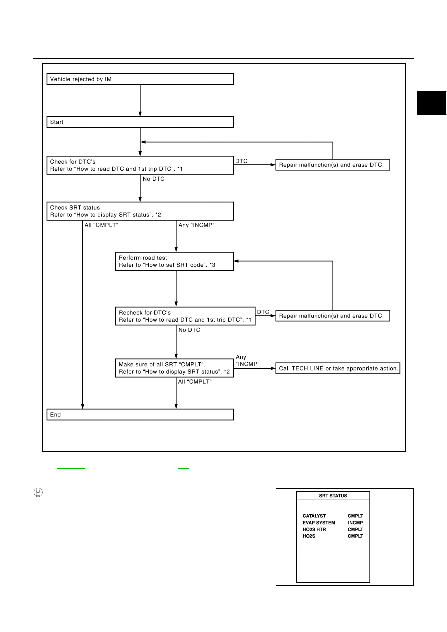
How to Display SRT Status
WITH CONSULT-II
Selecting “SRT STATUS” in “DTC CONFIRMATION” mode with
CONSULT-II.
For items whose SRT codes are set, a “CMPLT” is displayed on the
CONSULT-II screen; for items whose SRT codes are not set,
“INCMP” is displayed.
A sample of CONSULT-II display for SRT code is shown in the fig-
ure.
“INCMP” means the self-diagnosis is incomplete and SRT is not set.
“CMPLT” means the self-diagnosis is complete and SRT is set.
*1
EC-761, "How to Read DTC and 1st
Trip DTC"
*2
EC-765, "How to Display SRT Sta-
tus"
*3
PBIB2320E
SEF935Z
EC-766
[VK45DE]
ON BOARD DIAGNOSTIC (OBD) SYSTEM
NOTE:
Though displayed on the CONSULT-II screen, “HO2S HTR” is not SRT item.
WITH GST
Selecting Service $01 with GST (Generic Scan Tool)
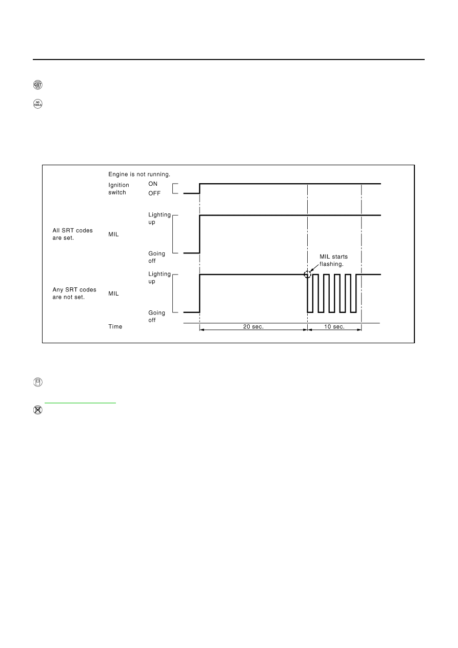
NO TOOLS
A SRT code itself can not be displayed while only SRT status can be.
1.
Turn ignition switch ON and wait 20 seconds.
2.
SRT status is indicated as shown below.
●
When all SRT codes are set, MIL lights up continuously.
●
When any SRT codes are not set, MIL will flash periodically for 10 seconds.
How to Set SRT Code
To set all SRT codes, self-diagnosis for the items indicated above must be performed one or more times. Each
diagnosis may require a long period of actual driving under various conditions.
WITH CONSULT-II
Perform corresponding DTC Confirmation Procedure one by one based on Performance Priority in the table
on
WITHOUT CONSULT-II
The most efficient driving pattern in which SRT codes can be properly set is explained on the next page. The
driving pattern should be performed one or more times to set all SRT codes.
PBIB2317E

ON BOARD DIAGNOSTIC (OBD) SYSTEM
EC-767
[VK45DE]
C
D
E
F
G
H
I
J
K
L
M
A
EC
Driving Pattern
PBIB2906E
EC-768
[VK45DE]
ON BOARD DIAGNOSTIC (OBD) SYSTEM
●
The time required for each diagnosis varies with road surface conditions, weather, altitude, individual driv-
ing habits, etc.
Zone A refers to the range where the time, required for the diagnosis under normal conditions*, is the
shortest.
Zone B refers to the range where the diagnosis can still be performed if the diagnosis is not completed
within zone A.
*: Normal conditions refer to the following:
●
Sea level
●
Flat road
●
Ambient air temperature: 20 - 30
°
C (68 - 86
°
F)
●
Diagnosis is performed as quickly as possible under normal conditions.
Under different conditions [For example: ambient air temperature other than 20 - 30
°
C (68 - 86
°
F)], diag-
nosis may also be performed.
Pattern 1:
●
The engine is started at the engine coolant temperature of
−
10 to 35
°
C (14 to 95
°
F)
(where the voltage between the ECM terminal 73 and ground is 3.0 - 4.3V).
●
The engine must be operated at idle speed until the engine coolant temperature is greater than
70
°
C (158
°
F) (where the voltage between the ECM terminal 73 and ground is lower than 1.4V).
●
The engine is started at the fuel tank temperature of warmer than 0
°
C (32
°
F) (where the voltage
between the ECM terminal 107 and ground is less than 4.1V).
Pattern 2:
●
When steady-state driving is performed again even after it is interrupted, each diagnosis can be con-
ducted. In this case, the time required for diagnosis may be extended.
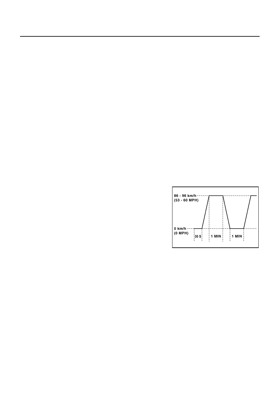
Pattern 3:
●
Operate vehicle following the driving pattern shown in the figure.
●
Release the accelerator pedal during decelerating vehicle speed
from 90 km/h (56 MPH) to 0 km/h (0 MPH).
Pattern 4:
●
The accelerator pedal must be held very steady during steady-
state driving.
●
If the accelerator pedal is moved, the test must be conducted all
over again.
*1: Depress the accelerator pedal until vehicle speed is 90 km/h (56
MPH), then release the accelerator pedal and keep it released for
more than 10 seconds. Depress the accelerator pedal until vehicle
speed is 90 km/h (56 MPH) again.
*2: Checking the vehicle speed with GST is advised.
Suggested Transmission Gear Position
Set the selector lever in the D position with the overdrive switch turned ON.
PBIB2244E
Нет комментариевНе стесняйтесь поделиться с нами вашим ценным мнением.
Текст