Infiniti M35/M45 Y50. Manual — part 574
ON BOARD DIAGNOSTIC (OBD) SYSTEM
EC-769
[VK45DE]
C
D
E
F
G
H
I
J
K
L
M
A
EC
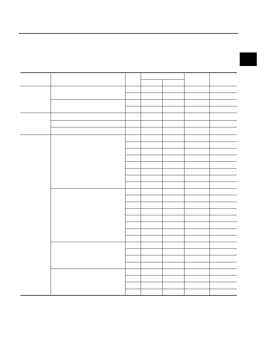
TEST VALUE AND TEST LIMIT (GST ONLY — NOT APPLICABLE TO CONSULT-II)
The following is the information specified in Service $06 of SAE J1979.
The test value is a parameter used to determine whether a system/circuit diagnostic test is OK or NG while
being monitored by the ECM during self-diagnosis. The test limit is a reference value which is specified as the
maximum or minimum value and is compared with the test value being monitored.
These data (test value and test limit) are specified by Test ID (TID) and Component ID (CID) and can be dis-
played on the GST screen.
Item
Self-diagnostic test item
DTC
Test value (GST display)
Test limit
Conversion
TID
CID
CATALYST
Three way catalyst function (Bank 1)
P0420
01H
01H
Max.
1/128
P0420
02H
81H
Min.
1
Three way catalyst function (Bank 2)
P0430
03H
02H
Max.
1/128
P0430
04H
82H
Min.
1
EVAP
SYSTEM
EVAP control system (Small leak)
P0442
05H
03H
Max.
1/128 mm
2
EVAP control system purge flow monitoring
P0441
06H
83H
Min.
20 mV
EVAP control system (Very small leak)
P0456
07H
03H
Max.
1/128 mm
2
HO2S
Air fuel ratio (A/F) sensor 1 (Bank 1)
P0131
41H
8EH
Min.
5mV
P0132
42H
0EH
Max.
5mV
P2A00
43H
0EH
Max.
0.002
P2A00
44H
8EH
Min.
0.002
P0133
45H
8EH
Min.
0.002
P0130
46H
0EH
Max.
5mV
P0130
47H
8EH
Min.
5mV
P0133
48H
8EH
Min.
0.002
Air fuel ratio (A/F) sensor 1 (Bank 2)
P0151
4CH
8FH
Min.
5mV
P0152
4DH
0FH
Max.
5mV
P2A03
4EH
0FH
Max.
0.002
P2A03
4FH
8FH
Min.
0.002
P0153
50H
8FH
Min.
0.002
P0150
51H
0FH
Max.
5mV
P0150
52H
8FH
Min.
5mV
P0153
53H
8FH
Min.
0.002
Heated oxygen sensor 2 (Bank 1)
P0139
19H
86H
Min.
10mV/500 ms
P0137
1AH
86H
Min.
10 mV
P0138
1BH
06H
Max.
10 mV
P0138
1CH
06H
Max.
10mV
Heated oxygen sensor 2 (Bank 2)
P0159
21H
87H
Min.
10 mV/500 ms
P0157
22H
87H
Min.
10 mV
P0158
23H
07H
Max.
10 mV
P0158
24H
07H
Max.
10mV
EC-770
[VK45DE]
ON BOARD DIAGNOSTIC (OBD) SYSTEM
HOW TO ERASE EMISSION-RELATED DIAGNOSTIC INFORMATION
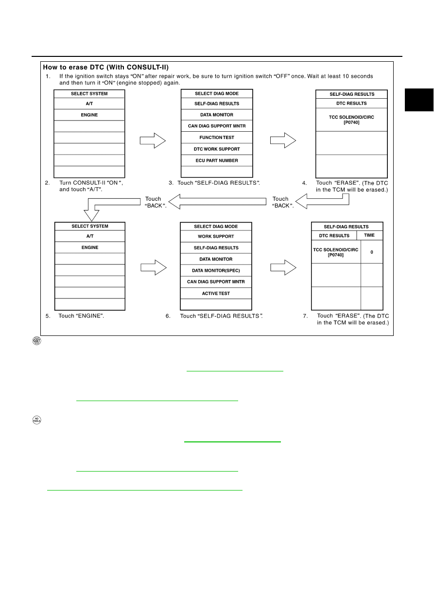
How to Erase DTC
WITH CONSULT-II
The emission related diagnostic information in the ECM can be erased by selecting “ERASE” in the “SELF-
DIAG RESULTS” mode with CONSULT-II.
If DTCs are displayed for both ECM and TCM (Transmission control module), they need to be erased individu-
ally from the ECM and TCM (Transmission control module).
NOTE:
If the DTC is not for A/T related items (see
), skip steps 2 through 4.
1.
If the ignition switch stays ON after repair work, be sure to turn ignition switch OFF once. Wait at least 10
seconds and then turn it ON (engine stopped) again.
2.
Turn CONSULT-II ON and touch “A/T”.
3.
Touch “SELF-DIAG RESULTS”.
4.
Touch “ERASE”. [The DTC in the TCM (Transmission control module) will be erased.] Then touch “BACK”
twice.
5.
Touch “ENGINE”.
6.
Touch “SELF-DIAG RESULTS”.
7.
Touch “ERASE”. (The DTC in the ECM will be erased.)
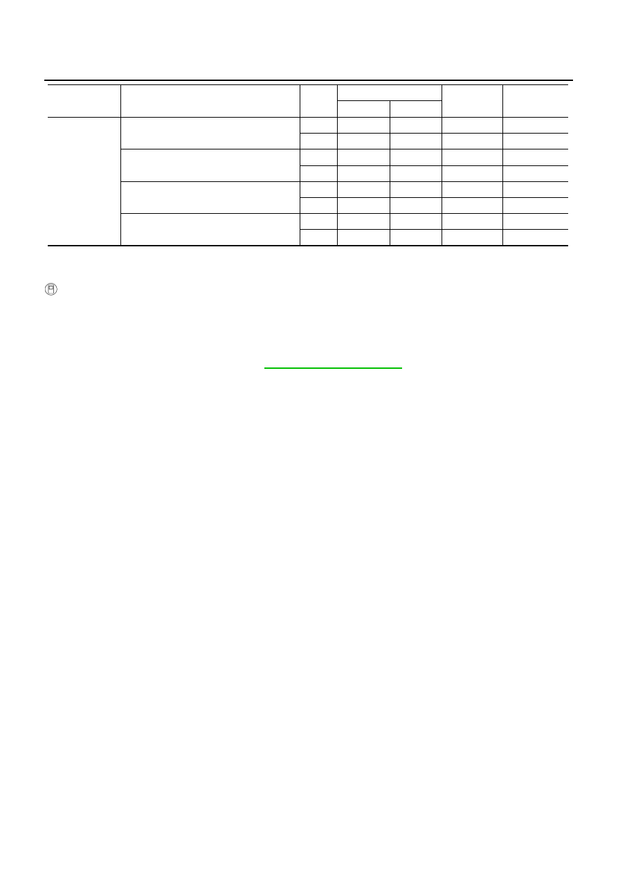
HO2S
HEATER
A/F sensor 1 heater (Bank 1)
P0032
57H
10H
Max.
5 mV
P0031
58H
90H
Min.
5 mV
A/F sensor 1 heater (Bank 2)
P0052
59H
11H
Max.
5 mV
P0051
5AH
91H
Min.
5 mV
Heated oxygen sensor 2 heater (Bank 1)
P0038
2DH
0AH
Max.
20 mV
P0037
2EH
8AH
Min.
20 mV
Heated oxygen sensor 2 heater (Bank 2)
P0058
2FH
0BH
Max.
20 mV
P0057
30H
8BH
Min.
20 mV
Item
Self-diagnostic test item
DTC
Test value (GST display)
Test limit
Conversion
TID
CID
ON BOARD DIAGNOSTIC (OBD) SYSTEM
EC-771
[VK45DE]
C
D
E
F
G
H
I
J
K
L
M
A
EC
WITH GST
The emission related diagnostic information in the ECM can be erased by selecting Service $04 with GST.
NOTE:
If the DTC is not for A/T related items (see
), skip step 2.
1.
If the ignition switch stays ON after repair work, be sure to turn ignition switch OFF once. Wait at least 10
seconds and then turn it ON (engine stopped) again.
2.
Perform
AT-40, "OBD-II Diagnostic Trouble Code (DTC)"
. (The DTC in TCM will be erased)
3.
Select Service $04 with GST (Generic Scan Tool).
No Tools
NOTE:
If the DTC is not for AT related items (see
1.
If the ignition switch stays ON after repair work, be sure to turn ignition switch OFF once.
Wait at least 10 seconds and then turn it ON (engine stopped) again.
2.
Perform
AT-40, "OBD-II Diagnostic Trouble Code (DTC)"
. (The DTC in the TCM will be erased.)
3.
Change the diagnostic test mode from Mode II to Mode I by depressing the accelerator pedal. Refer to
EC-773, "HOW TO SWITCH DIAGNOSTIC TEST MODE"
●
If the battery is disconnected, the emission-related diagnostic information will be lost within 24
hours.
●
The following data are cleared when the ECM memory is erased.
–
Diagnostic trouble codes
–
1st trip diagnostic trouble codes
–
Freeze frame data
–
1st trip freeze frame data
–
System readiness test (SRT) codes
SCIA5671E
EC-772
[VK45DE]
ON BOARD DIAGNOSTIC (OBD) SYSTEM
–
Test values
Actual work procedures are explained using a DTC as an example. Be careful so that not only the DTC, but all
of the data listed above, are cleared from the ECM memory during work procedures.
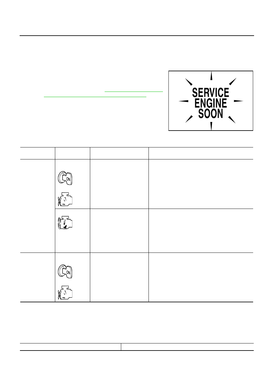
Malfunction Indicator Lamp (MIL)
NBS005A4
DESCRIPTION
The MIL is located on the instrument panel.
1.
The MIL will light up when the ignition switch is turned ON with-
out the engine running. This is a bulb check.
If the MIL does not light up, refer to
,
or see
EC-1438, "MIL AND DATA LINK CONNECTOR"
.
2.
When the engine is started, the MIL should go off.
If the MIL remains on, the on board diagnostic system has
detected an engine system malfunction.
ON BOARD DIAGNOSTIC SYSTEM FUNCTION
The on board diagnostic system has the following three functions.
When there is an open circuit on MIL circuit, the ECM cannot warn the driver by lighting up MIL when there is
malfunction on engine control system.
Therefore, when electrical controlled throttle and part of ECM related diagnoses are continuously detected as
NG for 5 trips, ECM warns the driver that engine control system malfunctions and MIL circuit is open by means
of operating fail-safe function.
The fail-safe function also operates when above diagnoses except MIL circuit are detected and demands the
driver to repair the malfunction.
SEF217U
Diagnostic Test
Mode
KEY and ENG.
Status
Function
Explanation of Function
Mode I
Ignition switch in
ON position
Engine stopped
BULB CHECK
This function checks the MIL bulb for damage (blown,
open circuit, etc.).
If the MIL does not come on, check MIL circuit.
Engine running
MALFUNCTION
WARNING
This is a usual driving condition. When a malfunction is
detected twice in two consecutive driving cycles (two trip
detection logic), the MIL will light up to inform the driver
that a malfunction has been detected.
The following malfunctions will light up or blink the MIL in
the 1st trip.
●
Misfire (Possible three way catalyst damage)
●
One trip detection diagnoses
Mode II
Ignition switch in
ON position
Engine stopped
SELF-DIAGNOSTIC
RESULTS
This function allows DTCs and 1st trip DTCs to be read.
Engine operating condition in fail-safe mode
Engine speed will not rise more than 2,500 rpm due to the fuel cut
Нет комментариевНе стесняйтесь поделиться с нами вашим ценным мнением.
Текст