Infiniti M35/M45 Y50. Manual — part 301
IVIS (INFINITI VEHICLE IMMOBILIZER SYSTEM-NATS)
BL-273
C
D
E
F
G
H
J
K
L
M
A
B
BL
7.
TROUBLE DIAGNOSIS
Repair IVIS (NATS) according to “SELF DIAGNOSIS”.
NOTE:
Do not erase “SELF DIAGNOSIS” using CONSULT-II.
>> GO TO 8.
8.
CONFIRM SELF DIAGNOSIS
Confirm SELF DIAGNOSIS “ECM” using CONSULT-II.
>> GO TO 9.
9.
CONFIRM SELF DIAGNOSIS DISPLAY
In case that malfunction of engine control system is displayed other than “NATS MALFUNCTION” in “SELF
DIAGNOSIS”, repair engine control system.
NOTE:
In case that only “NATS MALFUNCTION” is displayed, erase record of “SELF DIAGNOSIS”.
>> GO TO 10.
10.
CHECK ENGINE FOR START
Check that the engine can be started when Push-button ignition switch is operated with Intelligent Key
inserted into the key slot.
NG
>> GO TO 2.
OK
>> GO TO 11.
11.
CONFIRM SELF DIAGNOSIS
Confirm SELF DIAGNOSIS “ECM” using CONSULT-II.
“NO DTC” is displayed.>>Inspection END.
Malfunction information is displayed.>>GO TO 2.
BL-274
IVIS (INFINITI VEHICLE IMMOBILIZER SYSTEM-NATS)
Symptom Chart for Security Indicator
NIS0020Q
Security indicator does not turn ON or flash.
CAUTION:
●
Follow Trouble Diagnosis Flowchart referring to “Diagnosis Procedure”. Determine malfunction-
ing condition before performing this diagnosis.
●
Make sure that vehicle is under the condition shown in “Conditions of vehicle” before starting
diagnosis.
●
Check systems shown in the “Action” column in this order.
CONDITIONS OF VEHICLE (OPERATING CONDITIONS)
●
Intelligent Key is not inserted into key slot.
●
Engine switch is not depressed.
Check Security Indicator Harness
NIS0020R
1.
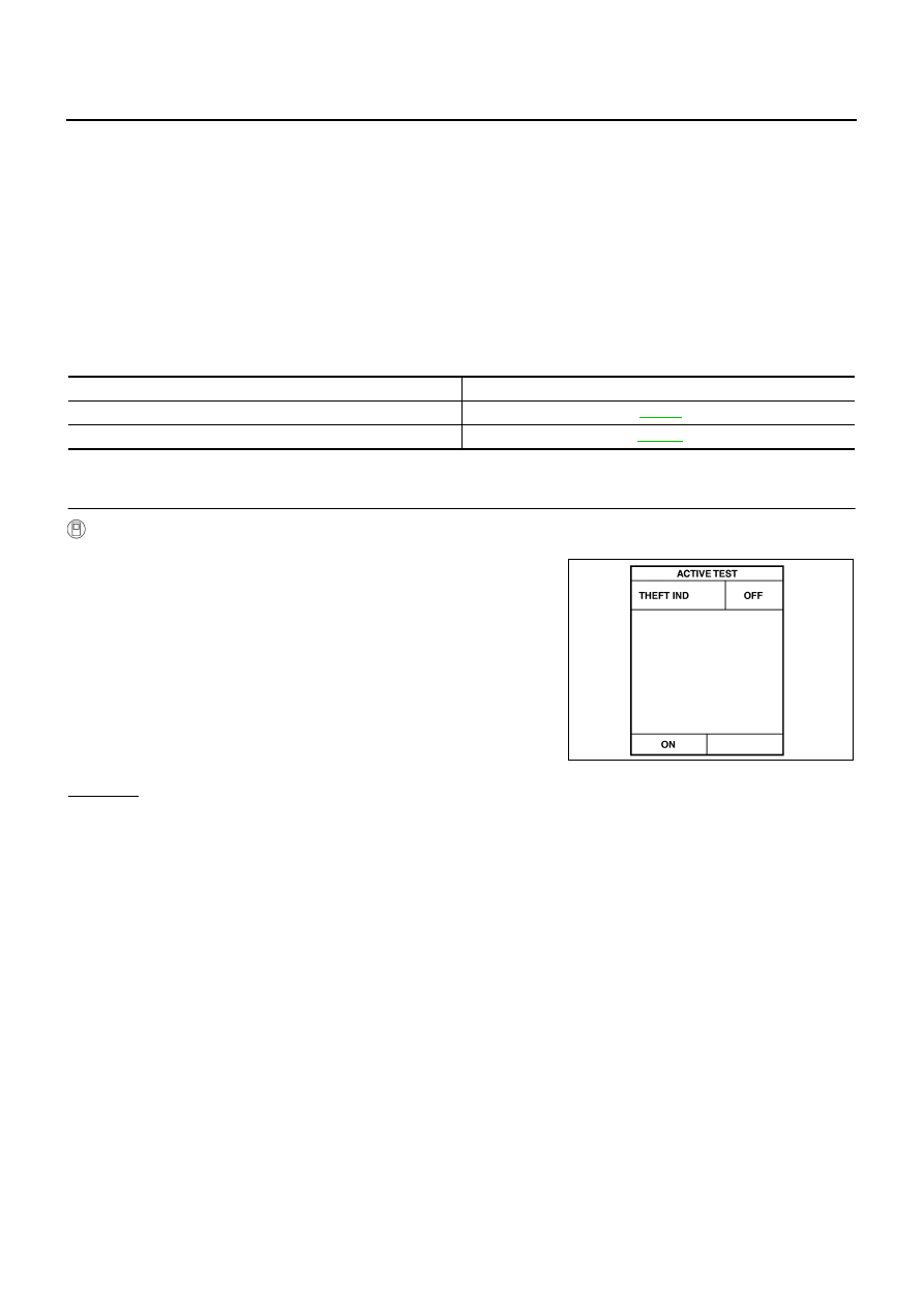
SECURITY INDICATOR LAMP ACTIVE TEST
With CONSULT-II
Check (“THEFT IND”) in “ACTIVE TEST” mode with CONSULT-II.
OK or NG
OK
>> Security indicator lamp is OK.
NG
>> GO TO 2.
Action
Reference page
1. Check security indicator harness
2. Replace BCM
Perform operation shown on display indicator lamp
should illuminate.
PIIA7005E
IVIS (INFINITI VEHICLE IMMOBILIZER SYSTEM-NATS)
BL-275
C
D
E
F
G
H
J
K
L
M
A
B
BL
2.
CHECK HARNESS CONTINUITY
1.
Turn ignition switch OFF.
2.
Disconnect multifunction switch (security indicator) connector.
3.
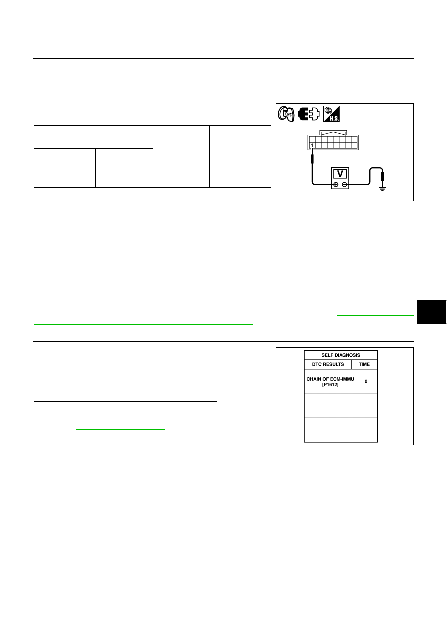
Check voltage between multifunction switch (security indicator)
connector and ground.
OK or NG
OK
>> Check the following.
●
Harness for open or short between BCM and multifunction switch (security indicator)
●
Security indicator lamp condition
NG
>> Check the following.
●
15A fuse [No.37, located in fuse block (J/B)]
●
Harness for open or short between multifunction switch (security indicator) and fuse
DTC P1612 CHAIN of ECM-IMMU
NIS0020S
Self-diagnostic results:
“CHAIN OF ECM-IMMU” displayed on CONSULT-II screen
First perform the “SELF-DIAG RESULTS” in “BCM” with CONSULT-II, then perform the trouble diagno-
sis of malfunction system indicated “SELF-DIAG RESULTS” of “BCM”. Refer to
munication Inspection Using CONSULT-II (Self-Diagnosis)"
1.
CONFIRM SELF-DIAGNOSTIC RESULTS
Confirm SELF-DIAGNOSTIC RESULTS “CHAIN OF ECM-IMMU”
displayed on CONSULT-II screen.
NOTE:
In rare case, “CHAIN OF ECM-IMMU” might be stored during key
registration procedure, even if the system is not malfunctioning.
Is CONSULT-II screen displayed as shown in figure?
Yes
>> GO TO 2.
No
BL-268, "“NATS V5.0” SELF-DIAGNOSTIC
.
Terminals
Voltage (V)
(Approx.)
(+)
(–)
multifunction switch
(security indicator)
connector
Terminal
M69
1
Ground
Battery voltage
PIIB6218E
PIIA1260E
BL-276
IVIS (INFINITI VEHICLE IMMOBILIZER SYSTEM-NATS)
2.
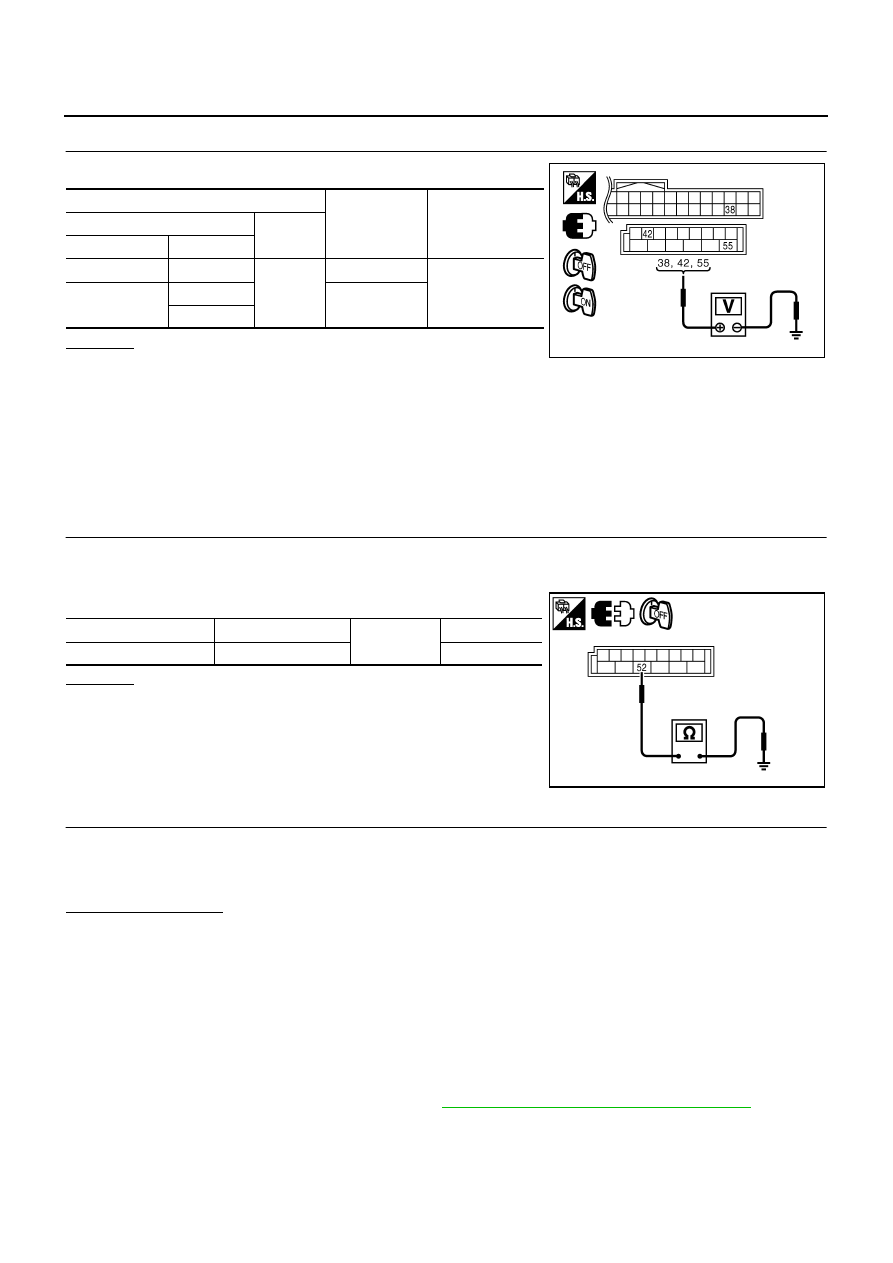
CHECK POWER SUPPLY CIRCUIT FOR BCM
Check voltage between BCM and ground with CONSULT-II or tester.
OK or NG
OK
>> GO TO 3.
NG
>> Check the following.
●
50A fusible link (letter F , located in the fuse and fusible link box)
●
10A fuse [No.21, located in the fuse block (J/B)]
●
15A fuse [No. 1, located in the fuse block (J/B)]
●
Harness for open or short between fusible link and BCM
●
Harness for open or short between fuse and BCM
3.
CHECK GROUND CIRCUIT FOR BCM
1.
Turn ignition switch OFF.
2.
Disconnect BCM connector.
3.
Check continuity between BCM connector and ground.
OK or NG
OK
>> GO TO 4.
NG
>> Repair or replace harness.
4.
REPLACE BCM
1.
Replace BCM
2.
Perform initialization with CONSULT-II.
For initialization, refer to “CONSULT-II Operation Manual NATS-IVIS/NVIS”.
Does the engine start?
Yes
>> BCM is malfunctioning.
●
Replace BCM.
●
Perform initialization with CONSULT-II
●
For initialization, refer to “CONSULT-II Operation Manual NATS-IVIS/NVIS”
No
>> ECM is malfunctioning.
●
Replace ECM.
●
Perform initialization or re-communicating function
●
For initialization, refer to “CONSULT-II Operation Manual NATS-IVIS/NVIS”
●
For re-communicating function, refer to
BL-248, "ECM Re-Communicating Function"
Terminals
Condition of
ignition switch
Voltage (V)
(Approx.)
(+)
(–)
BCM connector
Terminal
M1
38
Ground
ON
Battery voltage
M2
42
OFF
55
PIIB5934E
BCM connector
Terminal
Ground
Continuity
M2
52
Yes
PIIB5935E
Нет комментариевНе стесняйтесь поделиться с нами вашим ценным мнением.
Текст