Infiniti M35/M45 Y50. Manual — part 926
PARKING, LICENSE PLATE AND TAIL LAMPS
LT-249
C
D
E
F
G
H
I
J
L
M
A
B
LT
With the ignition switch in the ON or START position, power is supplied
●
to CPU located in IPDM E/R,
●
through 15A fuse [No. 1, located in fuse block (J/B)]
●
to BCM terminal 38.
With the ignition switch in the ACC or ON position, power is supplied
●
through 10A fuse [No. 6, located in fuse block (J/B)]
●
to BCM terminal 11.
Ground is supplied
●
to BCM terminal 52
●
through grounds M16 and M70,
●
to IPDM E/R terminals 38 and 51
●
through grounds E22 and E43.
OPERATION BY LIGHTING SWITCH
With the lighting switch in the 1ST or 2ND position (or if the auto light system is activated), the BCM receives
input signal requesting the parking, license plate and tail lamps to illuminate. This input signal is communi-
cated to the IPDM E/R across the CAN communication lines. The CPU located in the IPDM E/R controls the
tail lamp relay coil, which when energized, directs power
●
through IPDM E/R terminal 21
●
to front combination lamp LH and RH terminals 5 (parking)
●
to front combination lamp LH and RH terminals 7 (side marker)
●
to rear combination lamp LH and RH terminals 1 (tail and side marker)
●
to license plate lamp LH and RH terminals 1.
Ground is supplied at all times
●
to front combination lamp LH and RH terminals 1 (parking and side marker)
●
through grounds E22 and E43,
●
to rear combination lamp LH and RH terminals 4 (tail and side marker)
●
through grounds B5, B40 and B131.
●
to license plate lamp LH and RH terminals 2
●
through grounds B402 and B405.
With power and ground supplied, the parking, license plate and tail lamps illuminate.
COMBINATION SWITCH READING FUNCTION
Refer to
BCS-3, "COMBINATION SWITCH READING FUNCTION"
EXTERIOR LAMP BATTERY SAVER CONTROL
When the combination switch (lighting switch) is in the 1ST (or 2ND) position, and ignition switch is turned
from ON or ACC to OFF, battery saver control feature is activated.
Under this condition, parking, license plate, side marker and tail lamps remain illuminated for 5 minutes, then
the parking, license plate, side marker and tail lamps are turned off.
Exterior lamp battery saver control mode can be changed by the function setting of CONSULT-II.
CAN Communication System Description
NKS003SJ
CAN (Controller Area Network) is a serial communication line for real time application. It is an on-vehicle mul-
tiplex communication line with high data communication speed and excellent error detection ability. Many elec-
tronic control units are equipped onto a vehicle, and each control unit shares information and links with other
control units during operation (not independent). In CAN communication, control units are connected with 2
communication lines (CAN H line, CAN L line) allowing a high rate of information transmission with less wiring.
Each control unit transmits/receives data but selectively reads required data only.
CAN Communication Unit
NKS003SK
Refer to
LAN-50, "CAN System Specification Chart"
.
LT-250
PARKING, LICENSE PLATE AND TAIL LAMPS
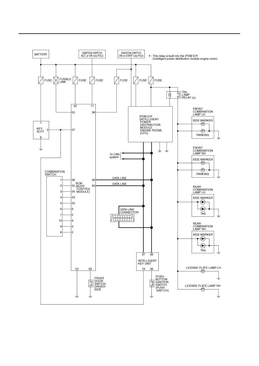
Schematic
NKS003SL
TKWT3391E
PARKING, LICENSE PLATE AND TAIL LAMPS
LT-251
C
D
E
F
G
H
I
J
L
M
A
B
LT
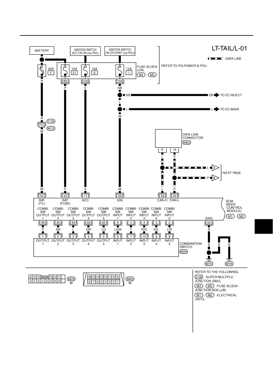
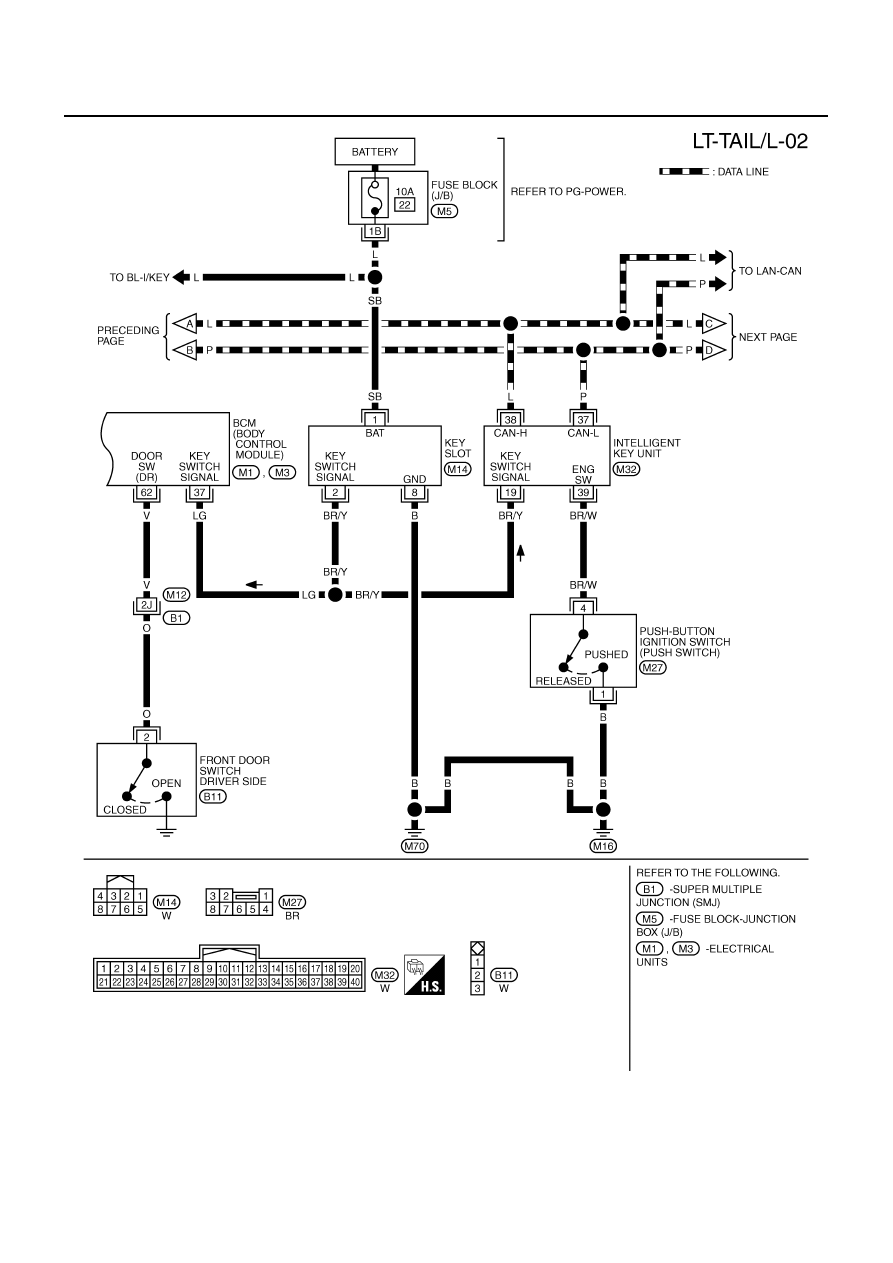
Wiring Diagram — TAIL/L —
NKS003SM
TKWT3392E
LT-252
PARKING, LICENSE PLATE AND TAIL LAMPS
TKWT5265E
Нет комментариевНе стесняйтесь поделиться с нами вашим ценным мнением.
Текст