Infiniti M35/M45 Y50. Manual — part 1044
STARTING SYSTEM
SC-11
C
D
E
F
G
H
I
J
L
M
A
B
SC
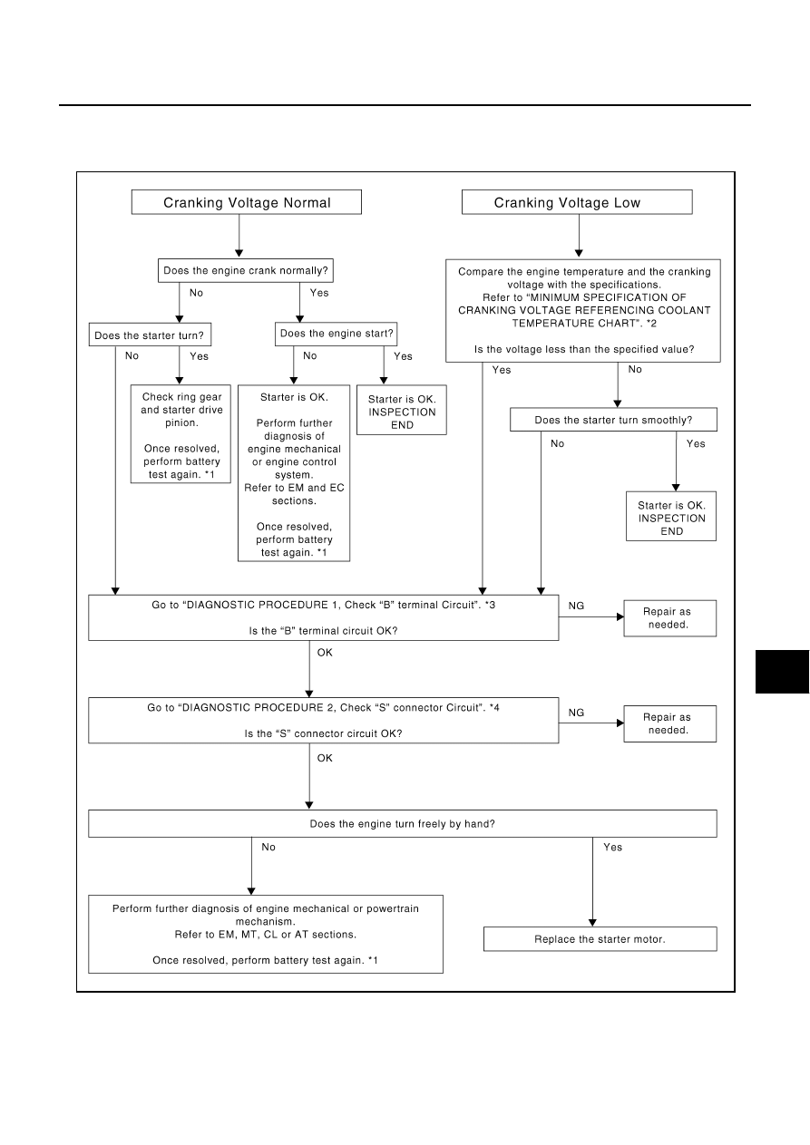
Trouble Diagnosis with Starting/Charging System Tester (Starting)
NKS005BT
For starting system testing, use Starting/Charging System Tester (J-44373). For details and operating instruc-
tions, refer to Technical Service Bulletin.
SKIB1369E
SC-12
STARTING SYSTEM
DIAGNOSTIC PROCEDURE 1
Check “B” Terminal Circuit
CAUTION:
Perform diagnosis under the condition that engine cannot start by the following procedure.
1.
Remove fuel pump fuse.
2.
Crank or start the engine (where possible) until the fuel pressure is released.
1.
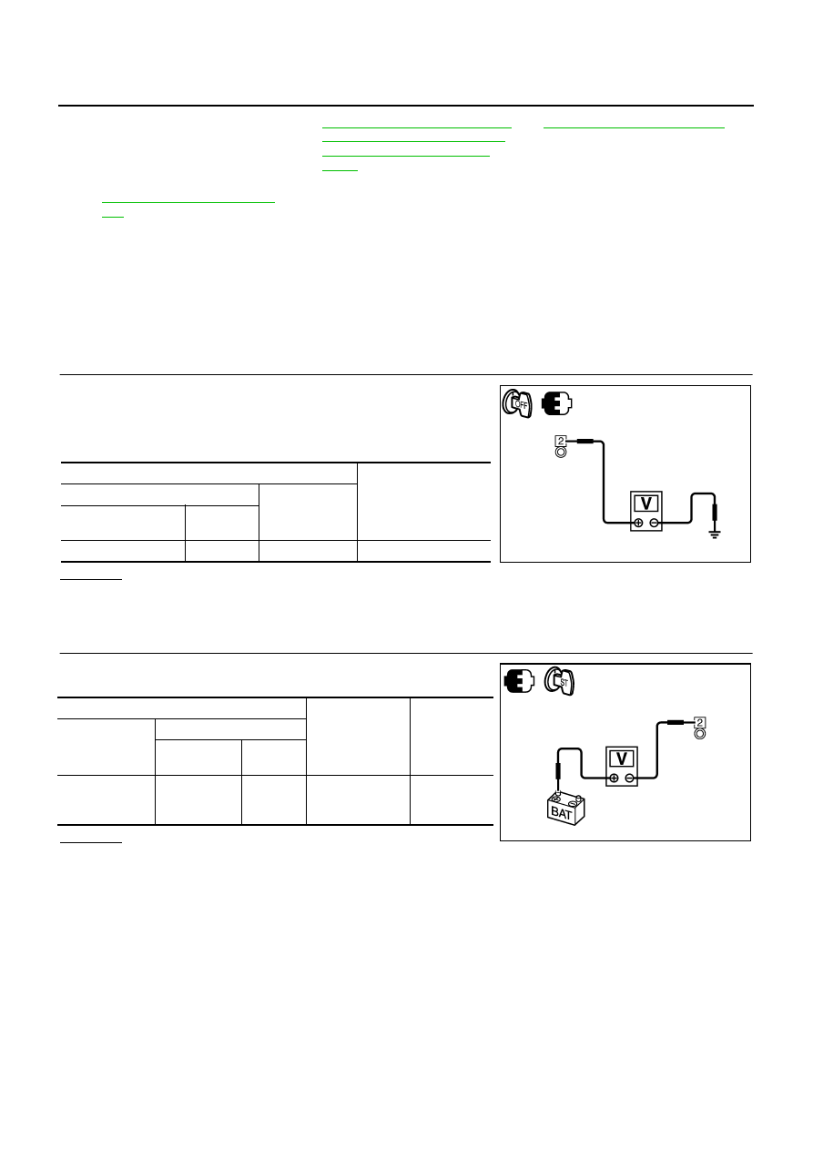
CHECK “B” TERMINAL CIRCUIT
1.
Turn ignition switch OFF.
2.
Make sure that starter motor “B” terminal connection is clean
and tight.
3.
Check voltage between starter motor “B” terminal and ground.
OK or NG
OK
>> GO TO 2.
NG
>> Check harness between battery and starter motor for open circuit.
2.
CHECK BATTERY CABLE CONNECTION STATUS (VOLTAGE DROP TEST)
Check voltage between starter motor “B” terminal and battery posi-
tive terminal.
OK or NG
OK
>> GO TO 3.
NG
>> Check harness between the battery and the starter motor for poor continuity.
*1
For battery testing, use Battery Ser-
vice Center (J-48087). For details
and operating instructions, refer to
Technical Service Bulletin and/or
Battery Service Center User Guide.
*2
SC-13, "MINIMUM SPECIFICATION
OF CRANKING VOLTAGE REFER-
ENCING COOLANT TEMPERA-
TURE"
*3
SC-12, "Check “B” Terminal Circuit"
*4
SC-13, "Check “S” Connector Cir-
cuit"
Terminals
Voltage (Approx.)
(+)
(–)
Starter motor
“B” terminal
Terminal
E203
2 Ground
Battery
voltage
PKIB8793E
Terminals
Condition
Voltage
(Approx.)
(+)
(–)
Starter motor
“B” terminal
Terminal
Battery positive
terminal
E203
2
When the ignition
switch is in
START position
Less than
0.5 V
PKIB8794E
STARTING SYSTEM
SC-13
C
D
E
F
G
H
I
J
L
M
A
B
SC
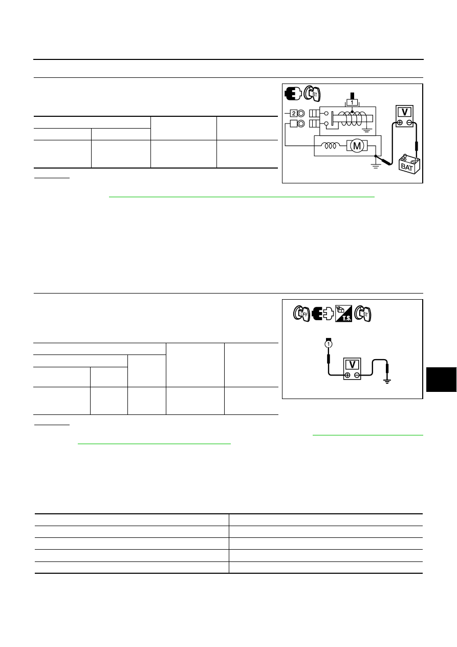
3.
CHECK GROUND CIRCUIT STATUS (VOLTAGE DROP TEST)
1.
Turn ignition switch OFF.
2.
Check voltage between starter motor case and battery negative
terminal.
OK or NG
OK
>> “B” terminal circuit is OK. Further inspection necessary.
Refer to
SC-11, "Trouble Diagnosis with Starting/Charging System Tester (Starting)"
NG
>> Check the starter motor case and ground for poor continuity.
DIAGNOSTIC PROCEDURE 2
Check “S” Connector Circuit
CAUTION:
Perform diagnosis under the condition that engine cannot start by the following procedure.
1.
Remove fuel pump fuse.
2.
Crank or start the engine (where possible) until the fuel pressure is released.
1.
CHECK “S” CONNECTOR CIRCUIT
1.
Turn ignition switch OFF.
2.
Disconnect starter motor connector.
3.
Check voltage between starter motor harness connector and
ground.
OK or NG
OK
>> “S” connector circuit is OK. Further inspection necessary. Refer to
SC-11, "Trouble Diagnosis with
Starting/Charging System Tester (Starting)"
NG
>> Check the following.
●
Ignition switch and PDU
●
IPDM E/R
●
Harness between starter motor and IPDM E/R
MINIMUM SPECIFICATION OF CRANKING VOLTAGE REFERENCING COOLANT TEMPERA-
TURE
Terminals
Condition
Voltage (Approx.)
(+)
(–)
Starter motor
case
Battery negative
terminal
When the ignition
switch is in
START position
Less than 0.2 V
PKIB8795E
Terminals
Condition
Voltage
(Approx.)
(+)
(–)
Starter motor
connector
Terminal
F9 (VQ35DE)
E210 (VK45DE)
1 Ground
When the ignition
switch is in
START position
Battery voltage
PKIB8796E
Engine coolant temperature
Voltage [V]
−
30
°
C to
−
20
°
C (
−
22
°
F to
−
4
°
F)
8.6
−
19
°
C to
−
10
°
C (
−
2
°
F to 14
°
F)
9.1
−
9
°
C to 0
°
C (16
°
F to 32
°
F)
9.5
More than 1
°
C (More than 34
°
F)
9.9
SC-14
STARTING SYSTEM
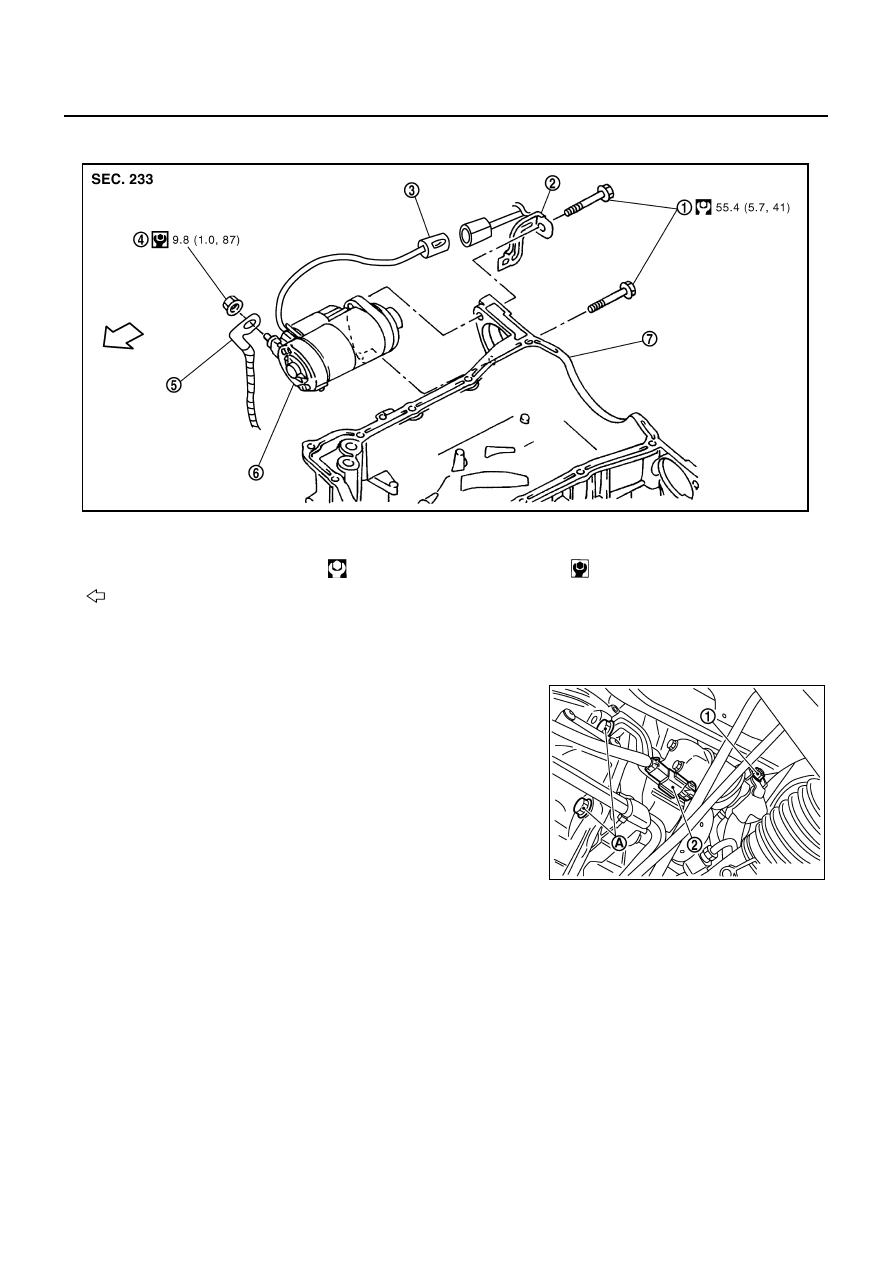
Removal and Installation
NKS005BU
VQ35DE ENGINE MODELS (2WD)
Removal
1.
Disconnect the battery cable from the negative terminal.
2.
Remove engine front and rear undercover, using power tools.
3.
Remove “B” terminal nut (1).
4.
Disconnect “S” connector (2).
5.
Remove starter motor mounting bolts (A), using power tools.
6.
Remove starter motor downward from the vehicle.
Installation
Installation is the reverse order of removal.
CAUTION:
Be sure to tighten “B” terminal nut carefully.
1.
Starter motor mounting bolt
2.
Harness clip bracket
3.
“S” connector
4.
“B” terminal nut
5.
“B” terminal harness
6.
Starter motor
7.
Oil pan
: N·m (kg-m, ft-lb)
: N·m (kg-m, in-lb)
: Engine front
PKIB8799E
PKIB8800E
Нет комментариевНе стесняйтесь поделиться с нами вашим ценным мнением.
Текст