Infiniti M35/M45 Y50. Manual — part 1043
BATTERY
SC-7
C
D
E
F
G
H
I
J
L
M
A
B
SC
Trouble Diagnosis with Battery Service Center
NKS005BP
For battery testing, use Battery Service Center (J-48087). For details and operating instructions, refer to Tech-
nical Service Bulletin and/or Battery Service Center User Guide.
Removal and Installation
NKS005BQ
REMOVAL
1.
Remove engine room cover RH.
2.
Remove battery cover.
3.
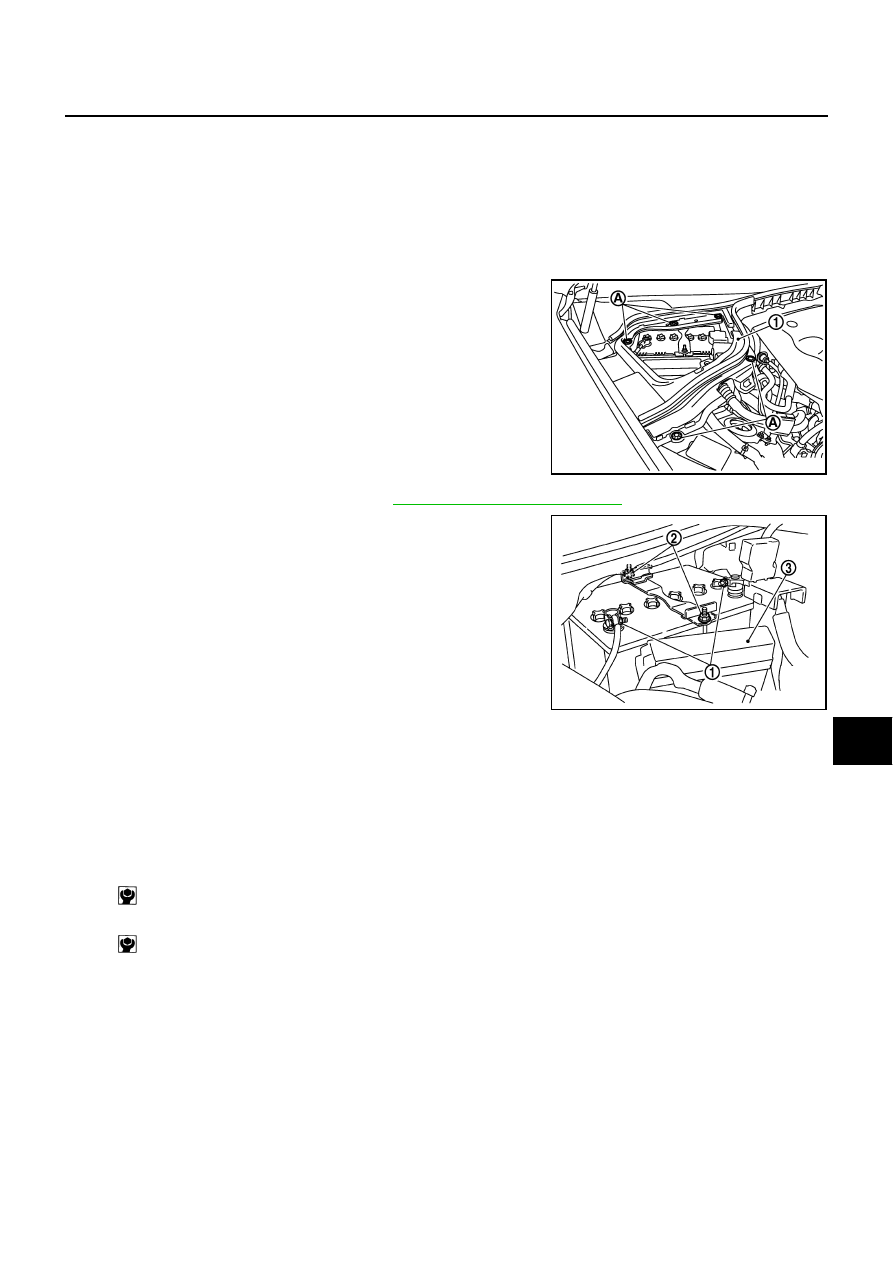
Remove the clips (A), and remove hoodledge cover RH (1).
4.
Remove the cowl top cover (RH). Refer to
EI-18, "Removal and Installation"
5.
Loosen battery terminal nuts (1), and disconnect both battery
cables from battery terminals.
CAUTION:
When disconnecting, disconnect the battery cable from the
negative terminal first.
6.
Remove battery fix frame mounting nuts (2) and battery fix
frame.
7.
Remove battery.
INSTALLATION
Installation is the reverse order of removal.
NOTE:
Locate the battery at the outside of the vehicle in the battery tray when installing the battery.
Check that the positive terminal cap opens and closes.
CAUTION:
When connecting, connect the battery cable to the positive terminal first.
PKIB8791E
3
: Relay box
PKIB8792E
Battery fix frame mounting nut
: 4.4 N·m (0.45 kg-m, 39 in-lb)
Battery terminal nut
: 5.4 N·m (0.55 kg-m, 48 in-lb)
SC-8
STARTING SYSTEM
STARTING SYSTEM
PFP:23300
System Description
NKS005C2
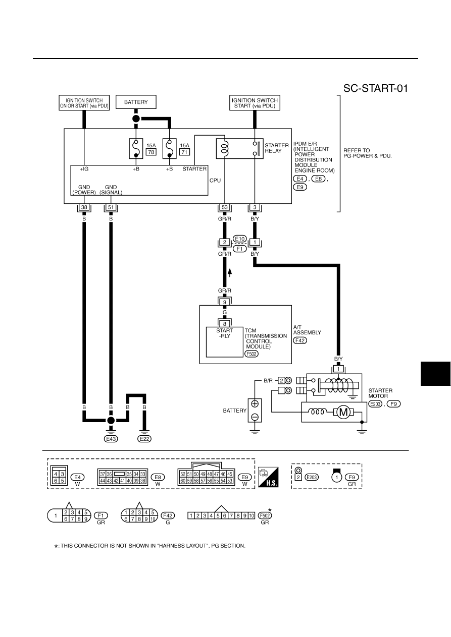
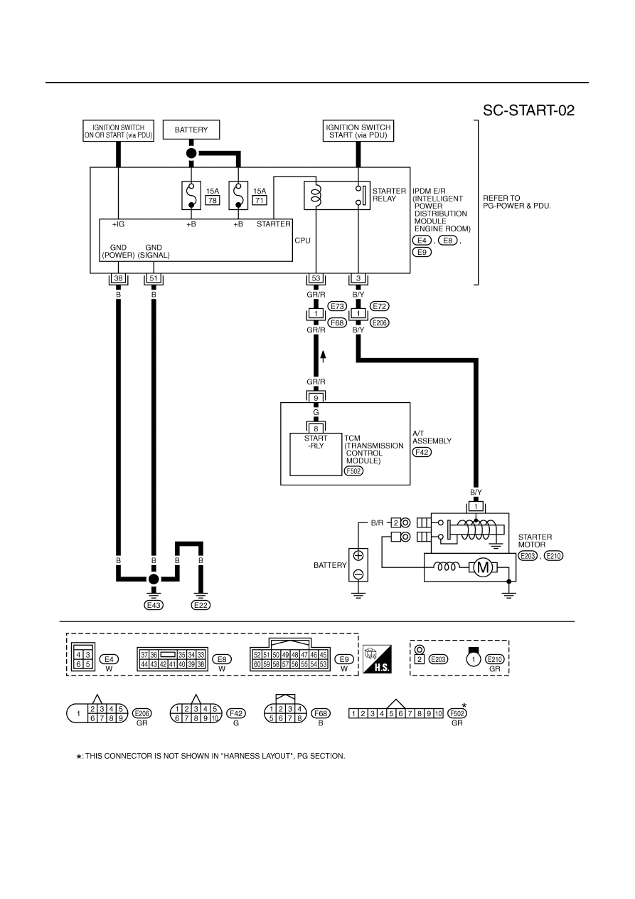
Power is supplied at all times
●
through 15A fuse (No. 78, located in the IPDM E/R)
●
to CPU of IPDM E/R,
●
through 15A fuse (No. 71, located in the IPDM E/R)
●
to CPU of IPDM E/R.
Ground is supplied
●
to IPDM E/R terminals 38 and 51
●
from grounds E22 and E43.
When the selector lever in the P or N position, power is supplied
●
from TCM, and through A/T assembly terminal 9
●
to IPDM E/R terminal 53.
And then provided that IPDM E/R receives a starter relay ON signal with CAN communication, starter relay is
energized.
With the ignition switch in the START position, power is supplied
●
through IPDM E/R terminal 3
●
to starter motor terminal 1.
The starter motor plunger closes and provides a closed circuit between the battery and starter motor. The
starter motor is grounded to the engine block. With power and ground supplied, cranking occurs and the
engine starts.
STARTING SYSTEM
SC-9
C
D
E
F
G
H
I
J
L
M
A
B
SC
Wiring Diagram — START —
NKS005C3
VQ35DE ENGINE MODELS
TKWT3232E
SC-10
STARTING SYSTEM
VK45DE ENGINE MODELS
TKWT3233E
Нет комментариевНе стесняйтесь поделиться с нами вашим ценным мнением.
Текст