Infiniti M35/M45 Y50. Manual — part 129
TROUBLE DIAGNOSIS
ATC-67
C
D
E
F
G
H
I
K
L
M
A
B
ATC
Power Supply and Ground Circuit for Auto Amp.
NJS000GL
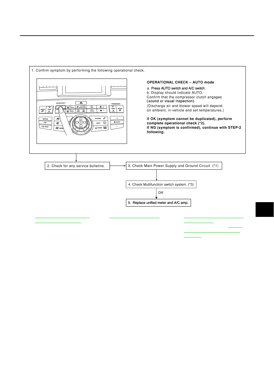
SYMPTOM: A/C system does not come on.
INSPECTION FLOW
*1
ATC-68, "DIAGNOSIS PROCE-
DURE FOR A/C SYSTEM"
*2
*3
AV-108, "Multifunction Switch Can-
not Be Operated"
(Without mobile
entertainment system) or
"Multifunction Switch Cannot Be
Operated"
(With mobile entertain-
ment system)
RJIA4047E
ATC-68
TROUBLE DIAGNOSIS
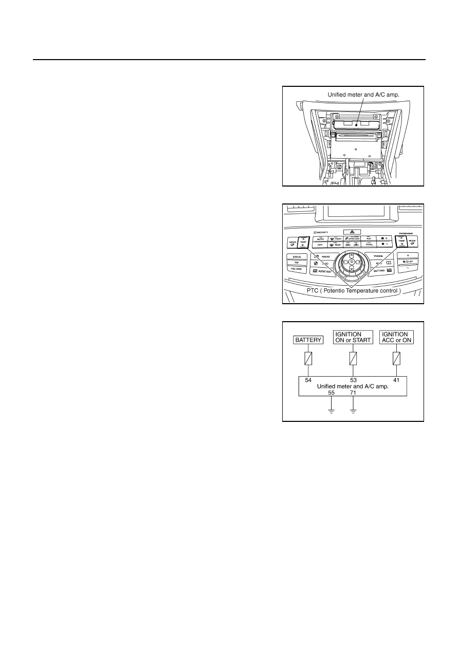
COMPONENT DESCRIPTION
Unified Meter and A/C Amp. (Automatic Amplifier)
The unified meter and A/C amp. has a built-in microcomputer which
processes information sent from various sensors needed for air con-
ditioner operation. The air mix door motor, mode door motor, upper
ventilator door motor, intake door motor, blower motor and compres-
sor are then controlled.
When the various switches and temperature control switch are oper-
ated, data is input to the unified meter and A/C amp. from the AV
control unit / NAVI control unit using CAN communication.
Self-diagnosis functions are also built into unified meter and A/C
amp. to provide quick check of malfunctions in the auto air condi-
tioner system.
Potentio Temperature Control (PTC)
The PTC is built into the multifunction switch. It can be set at an
interval of 0.5
°
C (1.0
°
F) in the 18
°
C (60
°
F) to 32
°
C (90
°
F) tempera-
ture range by pressing temperature control switch. The set tempera-
ture is displayed.
DIAGNOSIS PROCEDURE FOR A/C SYSTEM
SYMPTOM: A/C system does not come on.
RJIA4032E
RJIA4048E
RJIA4049E
TROUBLE DIAGNOSIS
ATC-69
C
D
E
F
G
H
I
K
L
M
A
B
ATC
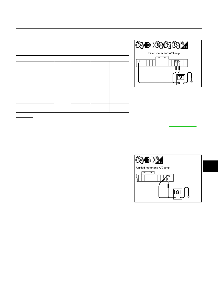
1.
CHECK POWER SUPPLY CIRCUIT FOR UNIFIED METER AND A/C AMP.
1.
Disconnect unified meter and A/C amp. connector.
2.
Check voltage between unified meter and A/C amp. harness
connector M65 terminals 41, 53 and 55 and ground.
OK or NG
OK
>> GO TO 2.
NG
>> Check 10A fuses [Nos. 6, 12 and 19, located in the fuse block (J/B)]. Refer to
●
If fuses are OK, check harness for open circuit. Repair or replace if necessary.
●
If fuses are NG, check harness for short circuit and replace fuse.
2.
CHECK GROUND CIRCUIT FOR UNIFIED METER AND A/C AMP.
1.
Turn ignition switch OFF.
2.
Check continuity between unified meter and A/C amp. harness
connector M65 terminal 55, 71 and ground.
OK or NG
OK
>> Replace unified meter and A/C amp.
NG
>> Repair harness or connector.
Terminals
Ignition switch position
(+)
(-)
OFF
ACC
ON
Unified
meter and
A/C amp.
connector
Terminal
No.
M65
41
Ground
Approx. 0 V
Battery
voltage
Battery
voltage
M65
53
Approx. 0 V
Approx. 0 V
Battery
voltage
M65
54
Battery
voltage
Battery
voltage
Battery
voltage
RJIA4050E
55, 71 – Ground
: Continuity should exist.
RJIA4051E
ATC-70
TROUBLE DIAGNOSIS
Rear Control Switch Circuit
NJS000GM
DIAGNOSIS PROCEDURE FOR REAR CONTROL SWITCH
SYMPTOM: Rear control switch does not operate.
1.
CHECK A/C SYSTEM
Check multifunction switch, confirm A/C system operation.
OK or NG
OK
>> GO TO 2.
NG
>> Go to trouble diagnosis procedure for A/C system. Refer to
ATC-67, "Power Supply and Ground
2.
CHECK REAR CONTROL SWITCH
Check rear control switch, except for A/C switch (audio) operation.
OK or NG
OK
>> GO TO 5.
NG
>> GO TO 3.
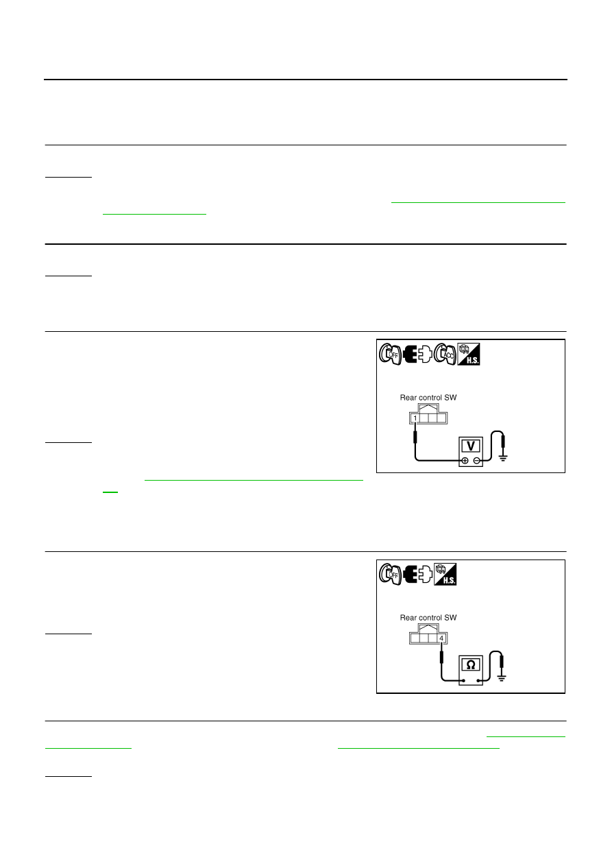
3.
CHECK POWER SUPPLY FOR REAR CONTROL SWITCH
1.
Turn ignition switch OFF.
2.
Disconnect rear control switch connector.
3.
Turn ignition switch ACC.
4.
Check voltage between rear control switch harness connector
B554 terminal 1 and ground.
OK or NG
OK
>> GO TO 4.
NG
>> Check 10A fuse [No. 6 located in the fuse block (J/B)].
Refer to
PG-114, "FUSE BLOCK - JUNCTION BOX (J/
.
●
If fuse is OK, check harness for open circuit. Repair or replace if necessary.
●
If fuse is NG, check harness for short circuit and replace fuse.
4.
CHECK GROUND CIRCUIT FOR REAR CONTROL SWITCH
1.
Turn ignition switch OFF.
2.
Check continuity between rear control switch harness connector
B554 terminal 4 and ground.
OK or NG
OK
>> GO TO 5.
NG
>> Repair harness or connector.
5.
CHECK REAR CONTROL SWITCH, AV CONTROL UNIT OR NAVI CONTROL UNIT
Check circuit between rear control switch and AV control unit or NAVI control unit. Refer to
(Without mobile entertainment system) or
(With mobile
entertainment system).
OK or NG
OK
>> Replace rear control switch.
NG
>> Replace part or repair for result trouble diagnosis.
1 – Ground
: Battery voltage
RJIA3996E
4 – Ground
: Continuity should exist.
RJIA3997E
Нет комментариевНе стесняйтесь поделиться с нами вашим ценным мнением.
Текст