Infiniti M35/M45 Y50. Manual — part 127
TROUBLE DIAGNOSIS
ATC-59
C
D
E
F
G
H
I
K
L
M
A
B
ATC
Checks must be made visually, by listening the sound, or by touching air outlets with hand, etc. for improper
operation.
*1: FOOT position during automatic control. Refer to
ATC-64, "AUXILIARY MECHANISM: FOOT POSITION
OK or NG
OK
>> GO TO 8.
NG
>>
●
Air outlet does not change.
Go to Mode Door Motor Circuit. Refer to
ATC-76, "Mode Door Motor Circuit"
●
Upper ventilator outlet does not change.
Go to Upper Ventilator Door Motor Circuit. Refer to
ATC-79, "Upper Ventilator Door Motor Cir-
●
Intake door does not change.
Go to Intake Door Motor Circuit. Refer to
ATC-85, "Intake Door Motor Circuit"
.
●
Discharge air temperature does not change.
Go to Air Mix Door Motor Circuit. Refer to
ATC-82, "Air Mix Door Motor Circuit"
●
Blower motor operation is malfunctioning.
Go to Blower Motor Circuit. Refer to
ATC-88, "Blower Motor Circuit"
.
●
Magnet clutch does not engage.
Go to Magnet Clutch Circuit. Refer to
ATC-93, "Magnet Clutch Circuit"
.
8.
STEP-5: TEMPERATURE OF EACH SENSOR IS CHECKED
1.
Press temperature control (UP) switch (driver side).
2.
Code No. 51 appears on the display.
>> GO TO 9.
9.
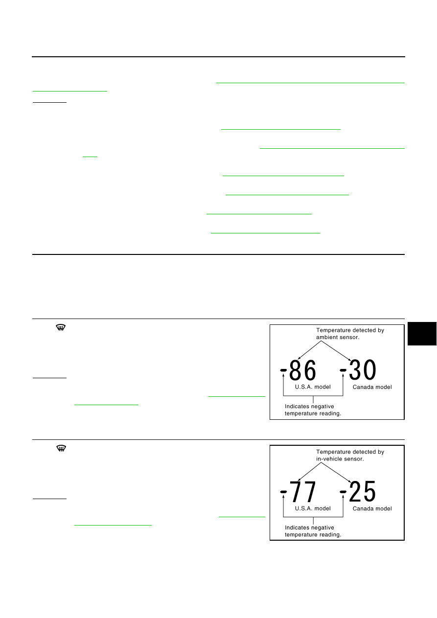
CHECK AMBIENT SENSOR
Press
(DEF) switch one time. Temperature detected by ambient
sensor is indicated on the display.
NOTE:
If the temperature indicated on the display greatly differs from the
actual temperature, check sensor circuit first, and then check sensor.
OK or NG
OK
>> GO TO 10.
NG
>> Go to Ambient Sensor Circuit. Refer to
10.
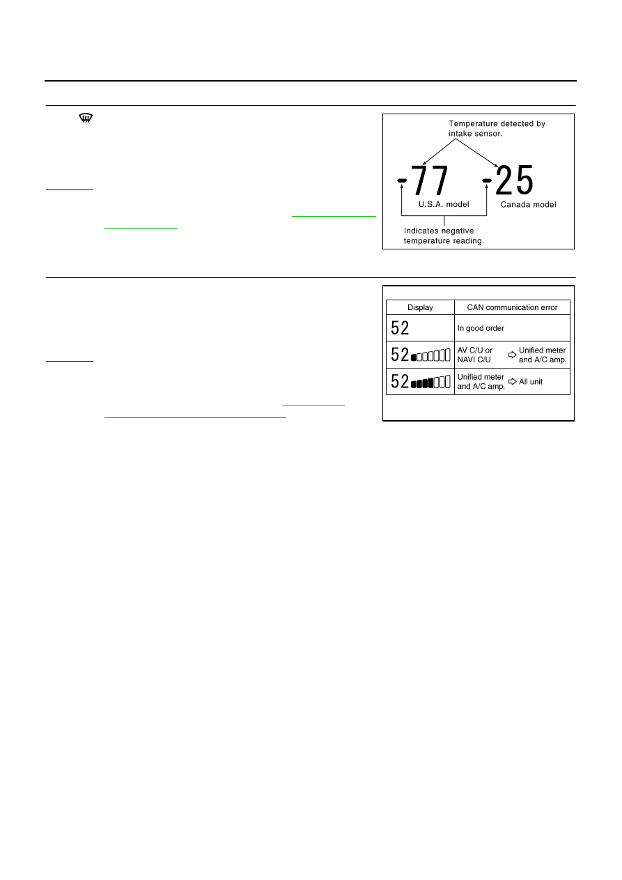
CHECK IN-VEHICLE SENSOR
Press
(DEF) switch for the second time. Temperature detected
by in-vehicle sensor is indicated on the display.
NOTE:
If the temperature indicated on the display greatly differs from the
actual temperature, check sensor circuit first, and then check sensor.
OK or NG
OK
>> GO TO 11.
NG
>> Go to In-vehicle Sensor Circuit. Refer to
PJIA0151E
PJIA0152E
ATC-60
TROUBLE DIAGNOSIS
11.
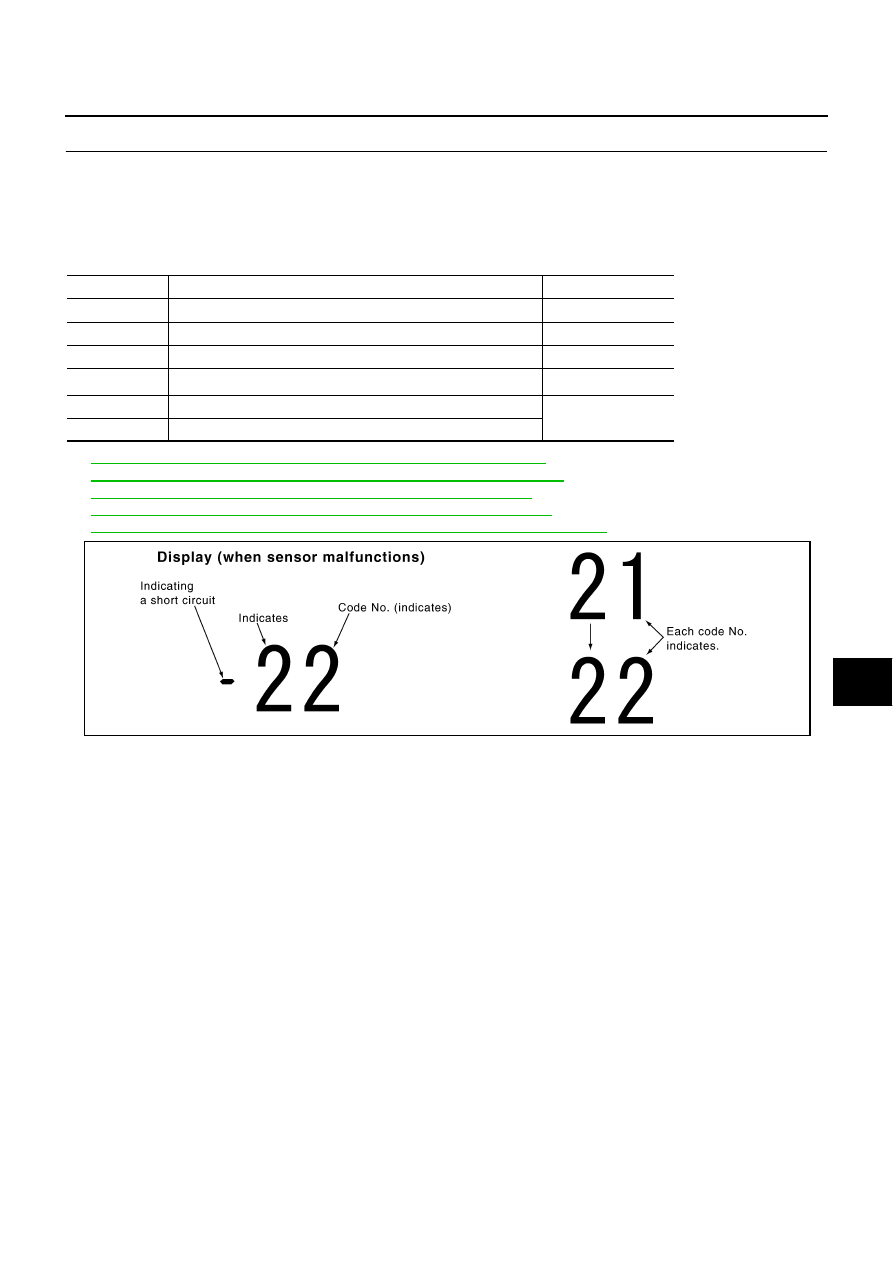
CHECK INTAKE SENSOR
Press
(DEF) switch for the third time. Temperature detected by
intake sensor is indicated on the display.
NOTE:
If the temperature indicated on the display greatly differs from the
actual temperature, check sensor circuit first, and then check sensor.
OK or NG
OK
>> GO TO 12.
NG
>> Go to Intake Sensor Circuit. Refer to
12.
CHECK CAN COMMUNICATION ERROR
1.
Press intake switch.
2.
CAN communication error between each unit that uses the uni-
fied meter and A/C amp. can be detected as self-diagnosis
results. (If plural errors occur, the display of each error will blink
twice for 0 - 5 second intervals.)
OK or NG
OK
>> 1. Turn ignition switch OFF or AUTO switch ON.
2. INSPECTION END
NG
>> Go to CAN communication. Refer to
[U1000] CAN Communication Circuit"
●
Unified meter and A/C amp. - AV control unit or NAVI
control unit
PJIA0153E
SJIA1763E
TROUBLE DIAGNOSIS
ATC-61
C
D
E
F
G
H
I
K
L
M
A
B
ATC
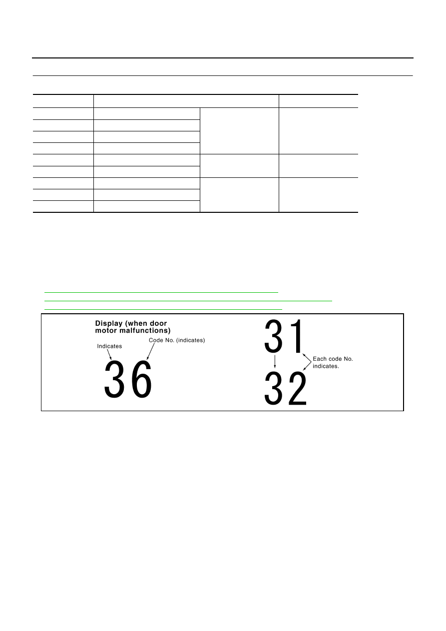
13.
CHECK MALFUNCTIONING SENSOR AND DOOR MOTOR
Refer to the following chart for malfunctioning code No.
(If two or more sensors and door motors malfunction, corresponding code Nos. indicates 1 second each.)
(If two door motors malfunction, corresponding code Nos. indicates 0.5 second each.)
*1: Perform self-diagnosis STEP-2 under sunshine.
When performing indoors, aim a light (more than 60 W) at sunload sensor, otherwise code No. 25 will indicate
despite that sunload sensor is functioning properly.
*2:
ATC-112, "DIAGNOSIS PROCEDURE FOR AMBIENT SENSOR"
*3:
ATC-116, "DIAGNOSIS PROCEDURE FOR IN-VEHICLE SENSOR"
*4:
ATC-121, "DIAGNOSIS PROCEDURE FOR INTAKE SENSOR"
*5:
ATC-118, "DIAGNOSIS PROCEDURE FOR SUNLOAD SENSOR"
*6:
ATC-84, "DIAGNOSIS PROCEDURE FOR AIR MIX DOOR MOTOR PBR"
.
>> INSPECTION END
Code No.
Malfunctioning sensor and door motor (Including circuits)
Reference page
21 /
−
21
Ambient sensor
*2
22 /
−
22
In-vehicle sensor
*3
24 /
−
24
Intake sensor
*4
25 /
−
25
Sunload sensor
*1
*5
26 /
−
26
Air mix door motor PBR (Driver side)
*6
27 /
−
27
Air mix door motor PBR (Passenger side)
SJIA1781E
ATC-62
TROUBLE DIAGNOSIS
14.
CHECK MALFUNCTIONING DOOR MOTOR POSITION SWITCH
Door motor PBR is malfunctioning.
(If two or more door motors malfunction, corresponding code Nos. indicates 1 second each.)
*1: If mode door motor (driver and passenger side) harness connector is disconnected, the following display
pattern will appear.
31
→
32
→
33
→
34
→
Return to 31
*2: If upper ventilator door motor harness connector is disconnected, the following display pattern will appear.
35
→
36
→
Return to 35
*3: If intake door motor harness connector is disconnected, the following display pattern will appear.
37
→
38
→
39
→
Return to 37
*4:
ATC-78, "DIAGNOSIS PROCEDURE FOR MODE DOOR MOTOR"
*5:
ATC-81, "DIAGNOSIS PROCEDURE FOR UPPER VENTILATOR DOOR MOTOR"
*6:
ATC-87, "DIAGNOSIS PROCEDURE FOR INTAKE DOOR MOTOR"
>> INSPECTION END
Code No.
*1 *2 *3
Door position
Reference page
31
VENT (Driver side)
Mode door motor
*4
32
DEF (Driver side)
33
VENT (Passenger side)
34
DEF (Passenger side)
35
UPPER VENT (Open)
Upper ventilator door
motor
*5
36
UPPER VENT (Shut)
37
FRE
Intake door motor
*6
38
20% FRE
39
REC
SJIA1782E
Нет комментариевНе стесняйтесь поделиться с нами вашим ценным мнением.
Текст