Infiniti M35/M45 Y50. Manual — part 213
DIAGNOSIS SYSTEM
AV-229
[WITH MOBILE ENTERTAINMENT SYSTEM]
C
D
E
F
G
H
I
J
L
M
A
B
AV
DIAGNOSIS RESULTS
Check the applicable display in the following table, and then repair the malfunctioning parts.
Control Unit Is Red, Gray, or Yellow
Connection Line Between Units Is Yellow (Only 1 Line)
Switch color
Description
Possible malfunction/Action to take
Red
AV (NAVI) control unit malfunction is detected
Replace AV (NAVI) control unit
Refer to
AV-282, "AV (NAVI) Control Unit"
Yellow
(With NAVI)
●
Malfunction is detected on DVD-ROM drive pickup
lens in NAVI control unit
●
There is dirt and damage on the map disc
●
Map disc
●
NAVI control unit
Gray
(With NAVI)
DVD-ROM not inserted is detected
Insert map disc
Applicable parts
Description
Probable malfunction location
Control unit to Camera Cont.
Camera-connection recognition signal malfunc-
tion is detected
●
Camera control unit power supply and ground
circuit
●
Camera-connection recognition signal circuit
●
AV (NAVI) Control unit
●
Camera control unit
Control unit to GPS Antenna
GPS antenna connection malfunction is detected
●
GPS antenna feeder
●
GPS antenna
●
NAVI control unit
Control unit to DVD deck
●
DVD player power supply and ground circuit
malfunction is detected
●
Malfunction is detected on communication sig-
nal between DVD player and AV (NAVI) control
unit
●
DVD player power supply and ground circuit
●
DVD player
●
AV (NAVI) control unit
Control unit to Amplifier
●
BOSE amp power supply and ground circuit
malfunction is detected
●
Malfunction is detected on communication sig-
nal between BOSE amp and AV (NAVI) control
unit
●
BOSE amp power supply and ground circuit
●
BOSE amp
●
AV (NAVI) control unit
Control unit to Video Distrib-
utor
●
Video distributor power supply and ground cir-
cuit malfunction is detected
●
Malfunction is detected on communication sig-
nal between video distributor and AV (NAVI)
control unit
●
Video distributor power supply and ground cir-
cuit
●
Video distributor
●
AV (NAVI) control unit
Control unit to Front Display
●
Front display unit power supply and ground cir-
cuit malfunction is detected (The diagnosis
screen can be checked at rear display)
●
Malfunction is detected on communication cir-
cuit between front display unit and AV (NAVI)
control unit
●
Malfunction is detected on communication sig-
nal between front display unit and AV (NAVI)
control unit
●
Front display unit power supply and ground cir-
cuit
●
Front display unit
●
AV (NAVI) control unit
Control unit to Rear Switches
●
Rear control switch power supply and ground
circuit malfunction is detected
●
Malfunction is detected on communication sig-
nal between rear control switch and AV (NAVI)
control unit
●
Rear control switch power supply and ground
circuit
●
Rear control switch
●
AV (NAVI) control unit

AV-230
[WITH MOBILE ENTERTAINMENT SYSTEM]
DIAGNOSIS SYSTEM
Connection Line Between Units Is Yellow (2 or More Lines)
When 2 or more connection lines between control unit (AV control unit, NAVI control) and each unit are dis-
played in yellow, these communication system lines may be open or shorted. The malfunctioning parts can be
detected by the combination of the connection lines displayed in yellow.
Control unit to Audio unit
●
Audio unit power supply and ground circuit mal-
function is detected
●
Malfunction is detected on communication cir-
cuit between audio unit and rear control switch
(Models with rear control switch)
●
Malfunction is detected on communication cir-
cuit between audio unit and BOSE amp (Mod-
els without rear control switch)
●
Malfunction is detected on communication sig-
nal between audio unit and AV (NAVI) control
unit
●
Audio unit power supply and ground circuit
●
Communication circuit between rear control
switch and audio unit
●
Audio unit
●
Rear control switch (with rear control switch)
●
BOSE amp (without rear control switch)
●
AV (NAVI) Control unit
Video distributor to Rear Dis-
play
●
Rear display unit power supply and ground cir-
cuit malfunction is detected
●
Malfunction is detected on communication cir-
cuit between video distributor and rear display
unit
●
Malfunction is detected on communication sig-
nal between video distributor and rear display
unit
●
Rear display unit power supply and ground cir-
cuit
●
Rear display unit
●
Video distributor
●
Communication circuit between video distribu-
tor and rear display unit
Applicable parts
Description
Probable malfunction location
Applicable parts
Description
Probable malfunction location
Control unit to
●
Amplifier
●
Rear Switches
●
Audio unit
●
Malfunction is detected on communication cir-
cuit between multifunction switch and camera
control unit
●
Malfunction is detected on communication cir-
cuit between camera control unit and BOSE
amp
●
Communication circuit between multifunction
switch and camera control unit
●
Communication circuit between camera control
unit and BOSE amp
●
Multifunction switch
●
Camera control unit
●
BOSE amp
Control unit to
●
Amplifier
●
Audio unit
●
Malfunction is detected on communication cir-
cuit between multifunction switch and camera
control unit
●
Malfunction is detected on communication cir-
cuit between camera control unit and BOSE
amp
●
Communication circuit between multifunction
switch and camera control unit
●
Communication circuit between camera control
unit and BOSE amp
●
Multifunction switch
●
Camera control unit
●
BOSE amp
Control unit to
●
Rear Switches
●
Audio unit
Malfunction is detected on communication circuit
between BOSE amp and rear control switch
●
Communication circuit between BOSE amp and
rear control switch
●
BOSE amp
●
Rear control switch
DIAGNOSIS SYSTEM
AV-231
[WITH MOBILE ENTERTAINMENT SYSTEM]
C
D
E
F
G
H
I
J
L
M
A
B
AV
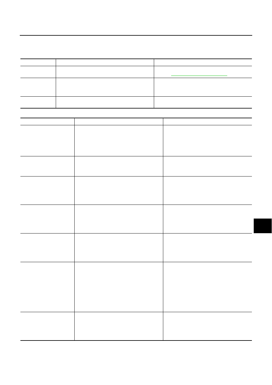
Confirmation/Adjustment Mode
NKS004AZ
1.
Confirmation/Adjustment mode can be selected by starting the
diagnosis function and selecting “Confirmation/Adjustment”. The
confirmation/adjustment of each item can be performed.
2.
Select each screen switch of Confirmation/Adjustment screen to
display the relevant diagnosis screen. Press the “BACK” switch
to return to the initial screen of Confirmation/Adjustment.
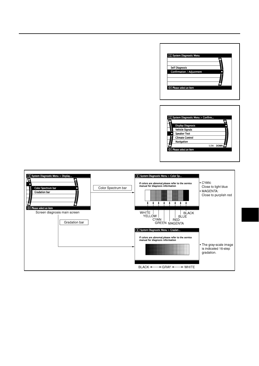
DISPLAY DIAGNOSIS
If RGB signal is malfunctioning, the tint of the color bar display is as follows.
SKIB3660E
SKIB3661E
SKIB3662E
R (red) signal error
: Light blue (Cyan) tint
G (green) signal error
: Purple (Magenta) tint
B (blue) signal error
: Yellow tint
AV-232
[WITH MOBILE ENTERTAINMENT SYSTEM]
DIAGNOSIS SYSTEM
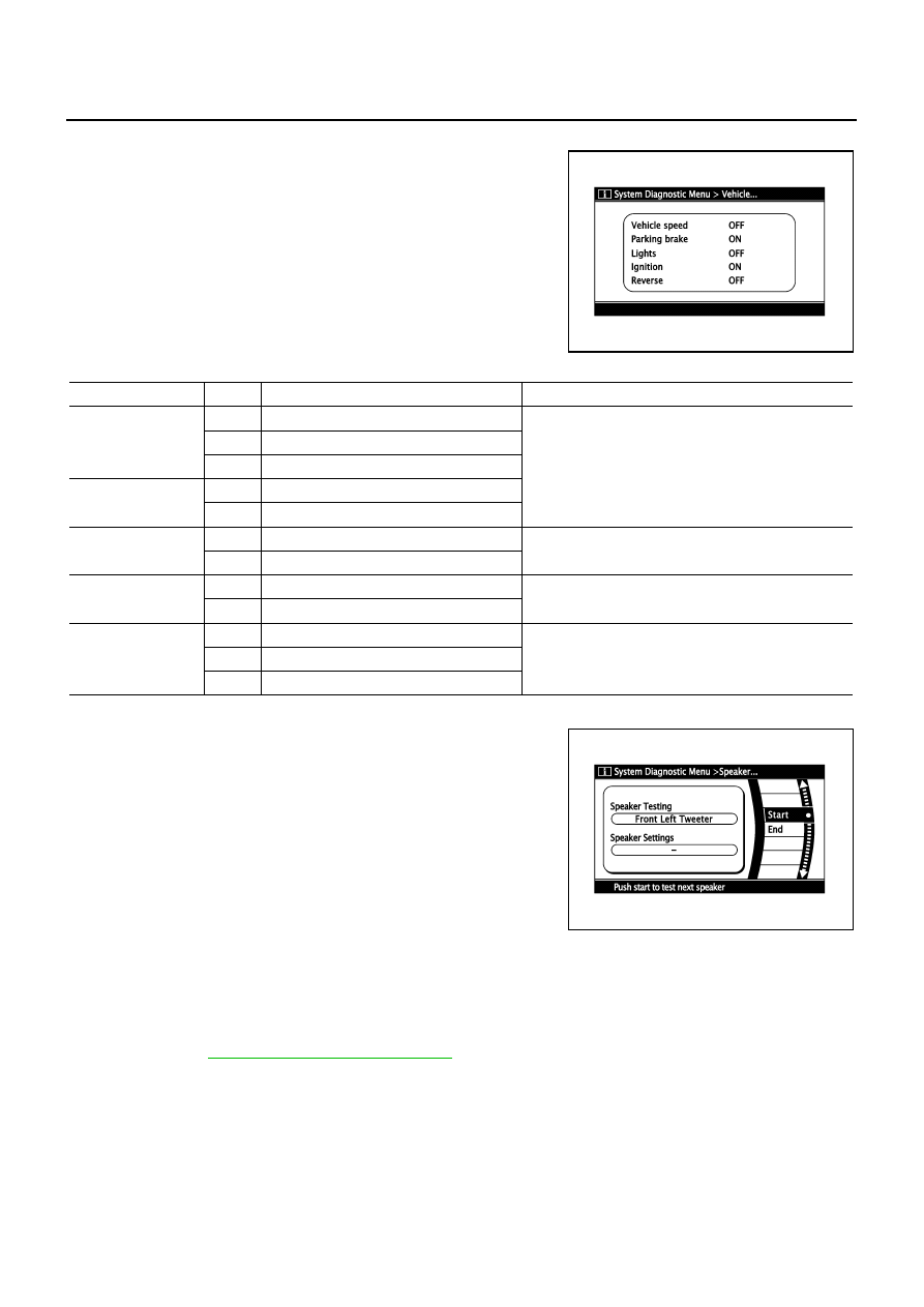
VEHICLE SIGNALS
A comparison check can be made of each actual vehicle signal and
the signals recognized by the system.
SPEAKER TEST
When selecting “Speaker Test”, speaker diagnosis screen is dis-
played. When pressing “Start”, test tone emits from the speaker. At
that time, when pressing “Start”, test tone emits from next speaker.
Then, when pressing the “End”, test tone stops.
NOTE:
The frequency of test tone emitted from each speaker is as follows.
CLIMATE CONTROL
ATC-56, "Self-diagnosis Function"
SKIB3663E
Diagnosis item
Display
Vehicle status
Remarks
Vehicle speed
ON
Vehicle speed > 0 km/h (0 MPH)
Changes in indication may be delayed by approxi-
mately 1.5 seconds. This is normal.
OFF
Vehicle speed = 0 km/h (0 MPH)
-
Ignition switch in ACC position
Parking brake
ON
Parking brake is applied.
OFF
Parking brake is released.
Lights
ON
Light switch ON
–
OFF
Light switch OFF
Ignition
ON
Ignition switch ON
-
OFF
Ignition switch in ACC position
Reverse
ON
Selector lever in R position
Changes in indication may be delayed by approxi-
mately 1.5 seconds. This is normal.
OFF
Selector lever in any position other than R
-
Ignition switch in ACC position
Tweeter
: 3 kHz
Front door speaker
: 300 Hz
Rear door speaker
: 1 kHz
Rear surround speaker
: 1 kHz
Center speaker
: 1 kHz
Woofer
: 100 Hz
Seat speaker
: 1 kHz
SKIB3664E
Нет комментариевНе стесняйтесь поделиться с нами вашим ценным мнением.
Текст