Infiniti M35/M45 Y50. Manual — part 211
TERMINALS AND REFERENCE VALUE FOR CONTROL UNIT
AV-221
[WITH MOBILE ENTERTAINMENT SYSTEM]
C
D
E
F
G
H
I
J
L
M
A
B
AV
*: BOSE surround 5.1ch system
33
*
(R/Y)
–
Shield
–
–
–
–
34
*
(R/L)
42
*
(G)
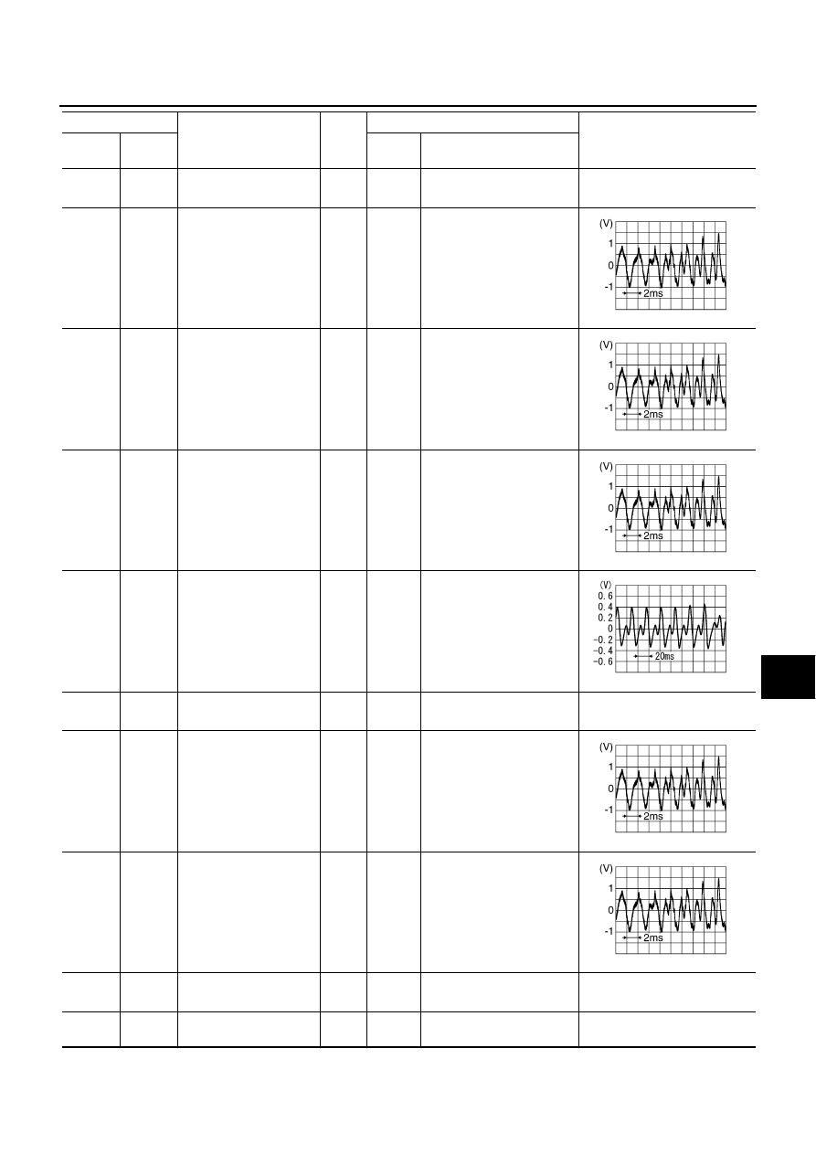
DVD sound signal front
RH
Output
ON
When playing DVD
CAUTION
35
*
(L/Y)
43
*
(L)
DVD sound signal front
LH
Output
ON
When playing DVD
CAUTION
36
*
(R/B)
44
*
(R)
DVD sound signal
center
Output
ON
When playing DVD
CAUTION
37
*
(Y/B)
45
*
(Y)
DVD sound signal woofer
Output
ON
When playing DVD
CAUTION
38
*
(G/R)
–
Shield
–
–
–
–
39
*
(Y/L)
47
*
(W/L)
DVD sound signal rear
RH
Output
ON
When playing DVD
CAUTION
40
*
(O/L)
48
*
(O)
DVD sound signal rear
LH
Output
ON
When playing DVD
CAUTION
46
*
(G/W)
–
Shield
–
–
–
–
49
(B)
Ground
Ground
–
ON
–
Approx. 0V
Terminal
Item
Signal
input/
output
Condition
Reference value
+
–
Ignition
switch
Operation
SKIB3609E
SKIB3609E
SKIB3609E
PKIB6116J
SKIB3609E
SKIB3609E
AV-222
[WITH MOBILE ENTERTAINMENT SYSTEM]
TERMINALS AND REFERENCE VALUE FOR CONTROL UNIT
CAUTION:
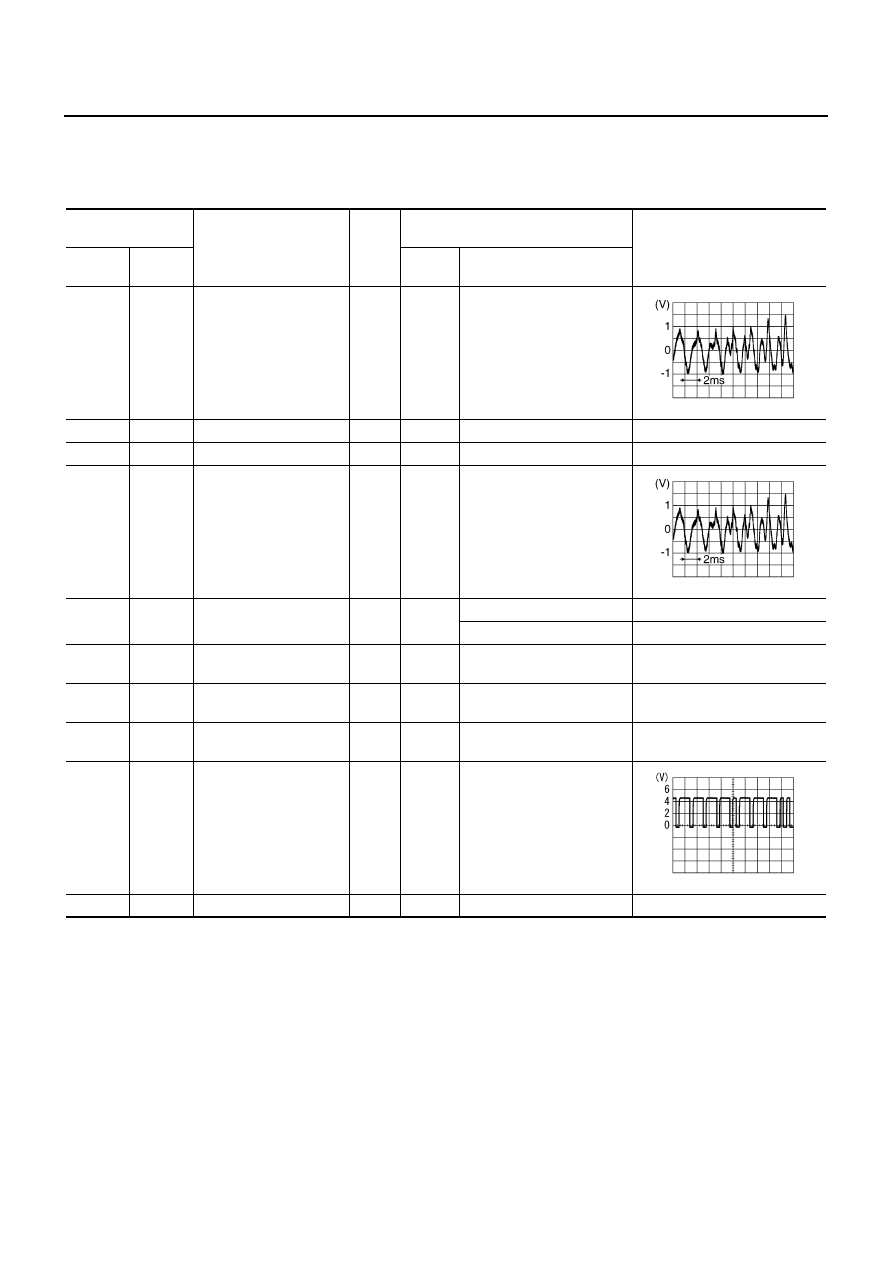
When the stereo sound is played, only front RH and LH are output. When the monaural sound is played, only center is output.
All surround sounds are input only when the 5.1 channel surround sound is played.
Headphone Amp
NKS004AT
Terminal
(Wire color)
Item
Signal
input/
output
Condition
Reference value
+
–
Ignition
switch
Operation
1
(W)
2
(B)
Headphone signal LH
Input
ON
When playing DVD
3
–
Shield
–
–
–
–
4
–
Shield
–
–
–
–
5
(L)
6
(G)
Headphone signal RH
Input
ON
When playing DVD
10
(L/W)
Ground
Headphone ON signal
Input
ON
Headphone mode is ON.
Approx. 4 V
Headphone mode is OFF.
Approx. 0 V
11
(B/W)
Ground
Ground
–
ON
–
Approx. 0 V
12
(Y)
Ground
Battery power supply
Input
OFF
–
Approx. 12 V
14
(W/L)
Ground
Remote control receiver
VCC
Input
ON
–
Approx. 5 V
15
(L/O)
Ground
Remote control signal
Output
ON
Rear seat remote controller
operation
16
–
Shield
–
–
–
–
SKIB3609E
SKIB3609E
PKIB6988J
TERMINALS AND REFERENCE VALUE FOR CONTROL UNIT
AV-223
[WITH MOBILE ENTERTAINMENT SYSTEM]
C
D
E
F
G
H
I
J
L
M
A
B
AV
Camera Control Unit
NKS004AU
Terminal
(wire color)
Item
Signal
input/
output
Condition
Reference value
+
–
Ignition
switch
Operation
5
–
Shield
–
–
–
–
6
(P/L)
Ground
Camera image signal
Input
ON
Set selector lever in R posi-
tion, and then display the
rear view image.
7
(G/B)
Ground
Camera ground
–
ON
–
Approx. 0 V
8
(GR)
Ground
Camera ON signal
Output
ON
Set selector lever in R posi-
tion, and then display the
rear view image.
Approx. 6 V
11
–
Shield
–
–
–
–
12
(Y)
Ground
Camera image signal
Output
ON
Set selector lever in R posi-
tion, and then display the
rear view image.
14
(V)
Ground
Camera-connection rec-
ognition signal
Output
ON
–
Approx. 0 V
17
(G)
–
Communication signal
(L)
Input/
Output
–
–
–
18
(R)
–
Communication signal
(H)
Input/
Output
–
–
–
19
(R)
–
Communication signal
(L)
Input/
Output
–
–
–
20
(W)
–
Communication signal
(H)
Input/
Output
–
–
–
22
(LG)
Ground
Reverse signal
Input/
Output
ON
Select lever in R position.
Approx. 12 V
Other than selector lever in
R position.
Approx. 0 V
SKIB0827E
SKIB0827E
AV-224
[WITH MOBILE ENTERTAINMENT SYSTEM]
TERMINALS AND REFERENCE VALUE FOR CONTROL UNIT
23
(L/Y)
Ground
Sensor signal 1
Input
ON
Turn the steering to the right
A: Sensor signal 1
B: Sensor signal 2
Turn the steering to the left
A: Sensor signal 1
B: Sensor signal 2
24
(B/R)
Ground
Sensor signal 2
Input
ON
Turn the steering to the right
A: Sensor signal 1
B: Sensor signal 2
Turn the steering to the left
A: Sensor signal 1
B: Sensor signal 2
25
(O)
Ground
Sensor signal 3
Input
ON
Turn the steering around the
neutral position
A: Sensor signal 3
B: Sensor signal 1
Terminal
(wire color)
Item
Signal
input/
output
Condition
Reference value
+
–
Ignition
switch
Operation
SKIB3827E
SKIB3828E
SKIB3827E
SKIB3828E
SKIB3829E
Нет комментариевНе стесняйтесь поделиться с нами вашим ценным мнением.
Текст