Infiniti M35/M45 Y50. Manual — part 1072
AUTOMATIC DRIVE POSITIONER
SE-85
C
D
E
F
G
H
J
K
L
M
A
B
SE
2.
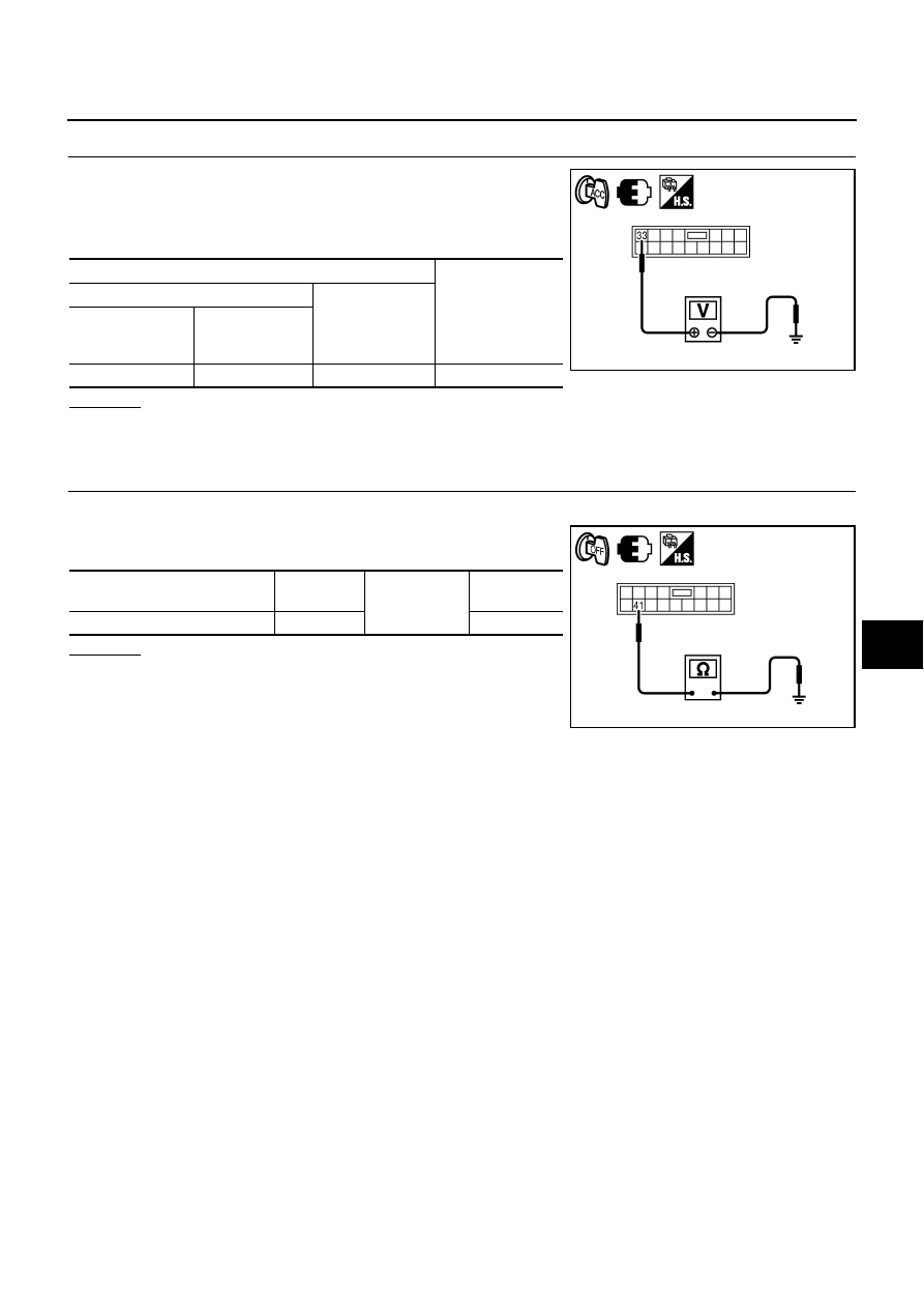
CHECK MIRROR SENSOR POWER SUPPLY
1.
Connect automatic drive positioner control unit connector.
2.
Turn ignition switch to ACC.
3.
Check voltage between automatic drive positioner control unit
connector and ground.
OK or NG
OK
>> GO TO 3.
NG
>> Replace automatic drive positioner control unit.
3.
CHECK MIRROR SENSOR GROUND CIRCUIT
1.
Turn ignition switch OFF.
2.
Check continuity between automatic drive positioner control unit
connector and ground.
OK or NG
OK
>> Door mirror power supply and ground circuit are OK.
NG
>> Replace automatic drive positioner control unit.
Terminals
Voltage (V)
(Approx.)
(+)
(–)
Automatic drive
positioner control
unit connector
Terminal
M6
33
Ground
5
PIIB6196E
Automatic drive positioner
control unit connector
Terminal
Ground
Continuity
M6
41
Yes
PIIB6197E
SE-86
AUTOMATIC DRIVE POSITIONER
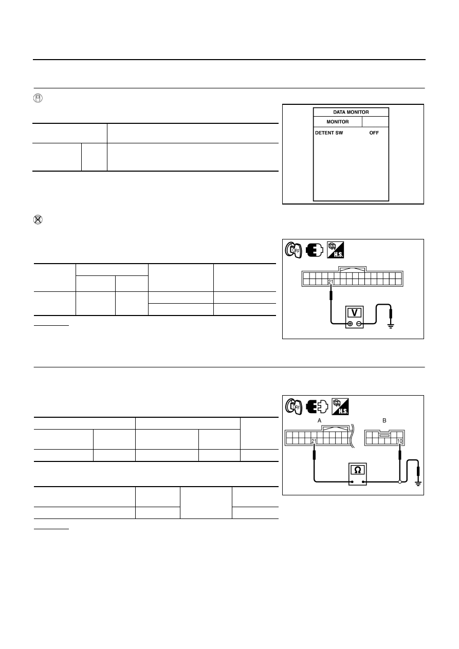
Check A/T Device (Detention Switch) Circuit
NIS0026V
1.
CHECK FUNCTION
With CONSULT-II
Check that when the A/T selector lever is in P position, “DETENT
SW” on the DATA MONITOR becomes OFF.
Without CONSULT-II
1.
Turn ignition switch OFF.
2.
Check voltage between driver seat control unit connector and
ground.
OK or NG
OK
>> A/T device (detention switch) circuit is OK.
NG
>> GO TO 2.
2.
CHECK A/T DEVICE (PARK POSITION SWITCH) HARNESS
1.
Turn ignition switch OFF.
2.
Disconnect A/T device and driver seat control unit connector.
3.
Check continuity between A/T device connector and driver seat
control unit connector.
4.
Check continuity between driver seat control unit connector and
ground.
OK or NG
OK
>> GO TO 3.
NG
>> Repair or replace harness.
Monitor item
[OPERATION or UNIT]
Contents
Detention SW
“ON/
OFF”
The selector lever position “P position (OFF)/other than P
position (ON)” judged from the detention switch signal is
displayed.
PIIB6293E
Driver seat
control unit
connector
Terminal
Condition of A/T
selector lever
Voltage (V)
(Approx.)
(+)
(–)
M204
21
Ground
P position
0
Other than above
Battery voltage
PIIB6198E
A
B
Continuity
Driver seat control
unit connector
Terminal
A/T device
connector
Terminal
M204
21
M133
10
Yes
Driver seat control unit
connector
Terminal
Ground
Continuity
M204
21
No
PIIB6199E

AUTOMATIC DRIVE POSITIONER
SE-87
C
D
E
F
G
H
J
K
L
M
A
B
SE
3.
CHECK PARK POSITION SWITCH
Check continuity between A/T device (detention switch) as follows.
OK or NG
OK
>> Check the condition of the harness and the connector.
NG
>> Replace A/T device.
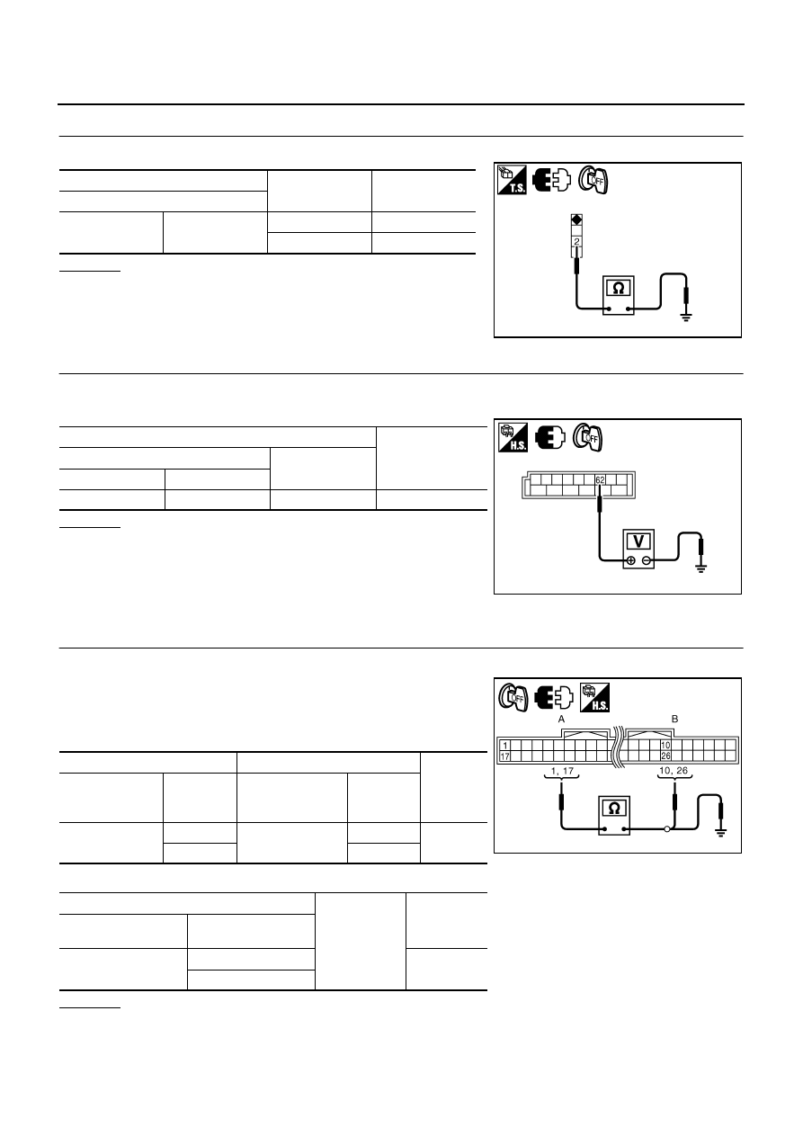
Check Front Door Switch (Driver Side) Circuit
NIS0026W
1.
CHECK DOOR SWITCH INPUT SIGNAL
1.
Turn ignition switch OFF.
2.
Check voltage between BCM connector and ground.
OK or NG
OK
>> Door switch circuit is OK.
NG
>> GO TO 2.
2.
CHECK HARNESS CONTINUITY
1.
Turn ignition switch OFF.
2.
Disconnect BCM and door switch (driver side) connector.
3.
Check continuity between BCM connector and door switch (driver side) connector.
4.
Check continuity between BCM connector ground.
OK or NG
OK
>> GO TO 3.
NG
>> Repair or replace harness.
A/T device
Terminals
Condition
Continuity
M133
9
10
P position
Yes
Other than
P position
No
PIIB6200E
Terminals
Door condition
Voltage (V)
(Approx.)
(+)
(–)
BCM
connector
Terminal
M3
62
Ground
Driver side
OPEN
0
CLOSE
Battery voltage
PIIB6295E
A
B
Continuity
BCM connector
Terminal
Door switch
connector
Terminal
M3
62
B11
2
Yes
A
Ground
Continuity
BCM connector
Terminal
M3
62
No
PIIB6294E
SE-88
AUTOMATIC DRIVE POSITIONER
3.
CHECK DOOR SWITCH
Check continuity door switch (driver side).
OK or NG
OK
>> GO TO 4.
NG
>> Replace door switch (driver side).
4.
CHECK BCM OUTPUT SIGNAL
1.
Connect BCM connector.
2.
Check voltage between BCM connector ground.
OK or NG
OK
>> Check the condition of the harness and the connector.
NG
>> Replace BCM.
Check UART Communication Line Circuit
NIS0026X
1.
CHECK UART LINE HARNESS
1.
Turn ignition switch OFF.
2.
Disconnect driver seat control unit and automatic drive posi-
tioner control unit connector.
3.
Check continuity between driver seat control unit connector and
automatic drive positioner connector.
4.
Check continuity between driver seat control unit connector and ground.
OK or NG
OK
>> GO TO 2.
NG
>> Repair or replace harness.
Terminal
Door switch
Continuity
Door switch
2
Ground part of
door switch
Pushed
No
Released
Yes
PIIB5977E
Terminal
Voltage (V)
(Approx.)
(+)
(–)
BCM connector
Terminal
M3
62
Ground
Battery voltage
PIIB6295E
A
B
Continuity
Driver seat control
unit connector
Terminal
Automatic drive
positioner control
unit connector
Terminal
B204
1
M6
10
Yes
17
26
A
Ground
Continuity
Driver seat control unit
connector
Terminal
B204
1
No
17
PIIB6201E
Нет комментариевНе стесняйтесь поделиться с нами вашим ценным мнением.
Текст