Infiniti M35/M45 Y50. Manual — part 1073
AUTOMATIC DRIVE POSITIONER
SE-89
C
D
E
F
G
H
J
K
L
M
A
B
SE
2.
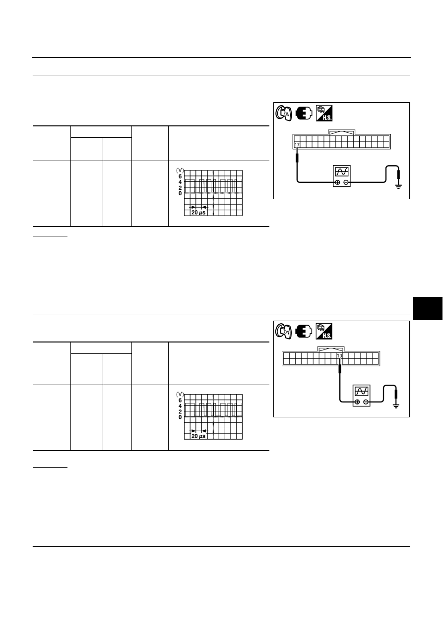
CHECK UART LINE INPUT/OUTPUT SIGNAL 1
1.
Connect driver seat control unit and automatic drive positioner control unit connector.
2.
Turn ignition switch ON.
3.
Check signal between driver seat control unit connector and
ground, with oscilloscope.
OK or NG
OK
>> GO TO 3.
NG
>> Check the following.
●
When voltage wave form does not appear with a constant voltage (approx. 5V), replace driver
seat control unit.
●
When voltage wave form does not appear with a constant voltage (approx. 0V), replace auto-
matic drive positioner control unit.
3.
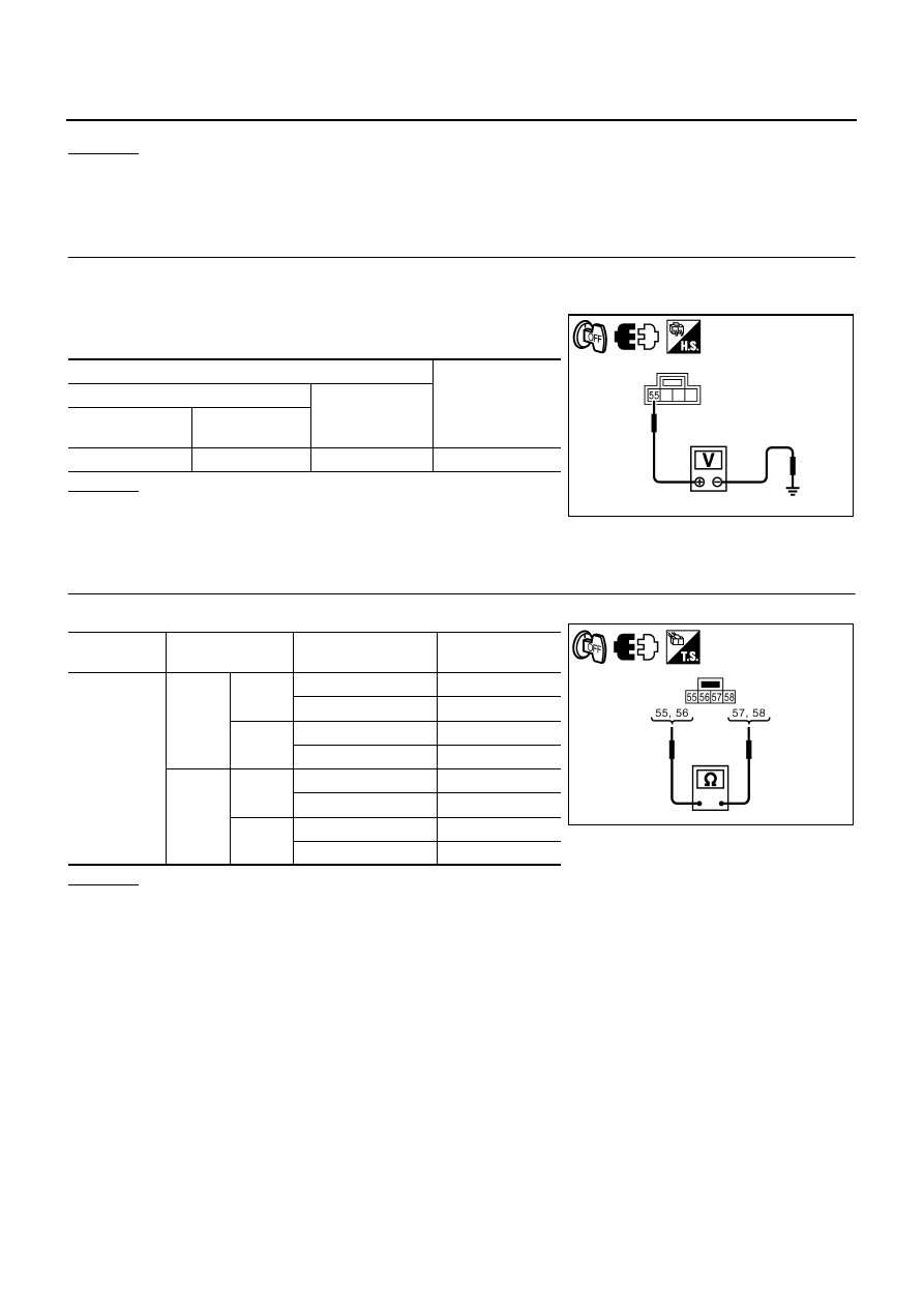
CHECK UART LINE INPUT/OUTPUT SIGNAL 2
Check signal between automatic drive positioner control unit con-
nector and ground, with oscilloscope.
OK or NG
OK
>> GO TO 4.
NG
>> Check the following.
●
When voltage wave form does not appear with a constant voltage (approx. 5V), replace auto-
matic drive positioner control unit.
●
When voltage wave form does not appear with a constant voltage (approx. 0V), replace driver
seat control unit.
4.
CHECK DRIVER SEAT CONTROL UNIT
Does the automatic drive positioner operate when the driver seat control unit is exchanged?
Driver seat
control
unit
connector
Terminals
Condition
Signal
(Reference value)
(+)
(–)
B204
17
Ground
Tilt switch
operated
PIIB6202E
SKIA0175E
Automatic
drive posi-
tioner con-
trol unit
connector
Terminals
Condition
Signal
(Reference value)
(+)
(–)
M6
10
Ground
Tilt switch
operated.
PIIB6203E
SKIA0175E
SE-90
AUTOMATIC DRIVE POSITIONER
OK or NG
OK
>> Replace driver seat control unit.
NG
>> Replace automatic drive positioner control unit.
Check Lumbar Support Circuit
NIS0026Y
1.
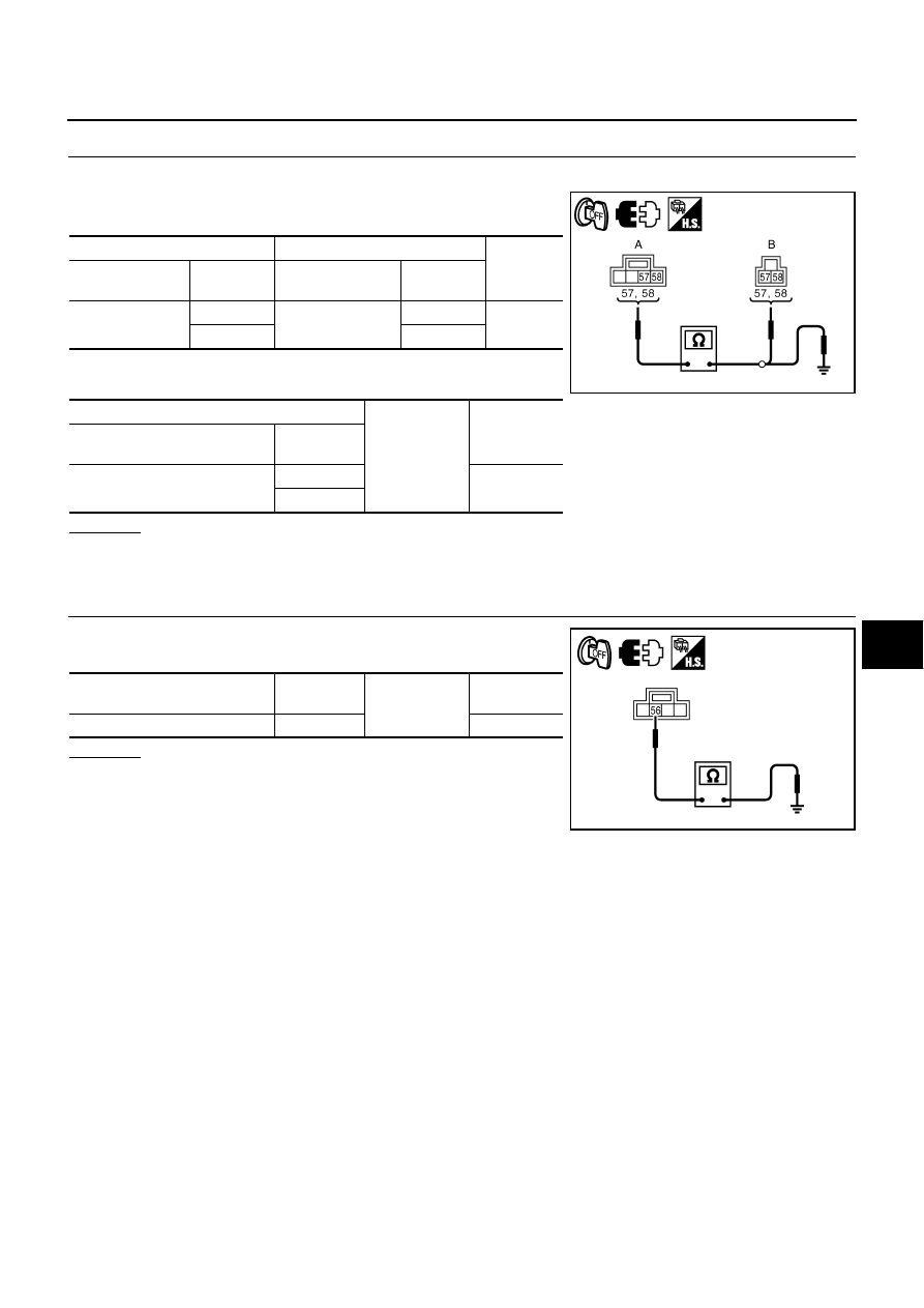
CHECK LUMBAR SUPPORT SWITCH
1.
Turn ignition switch OFF.
2.
Disconnect lumbar support switch connector.
3.
Check voltage between lumbar support switch connector and
ground.
OK or NG
OK
>> GO TO 2.
NG
>> Repair or replace harness between fuse block (J/B) and
lumbar support switch.
2.
CHECK LUMBAR SUPPORT SWITCH
Check continuity lumbar support switch connector.
OK or NG
OK
>> GO TO 3.
NG
>> Replace lumbar support switch.
Terminals
Voltage (V)
(Approx.)
(+)
(–)
Lumbar support
switch connector
Terminal
B212
55
Ground
Battery voltage
PIIB6204E
Lumbar
support switch
Terminal
Condition of
lumbar support switch
Continuity
B212
55
57
FORWARD
Yes
Other than above
No
58
BACKWARD
Yes
Other than above
No
56
57
FORWARD
No
Other than above
Yes
58
BACKWARD
No
Other than above
Yes
PIIB6205E
AUTOMATIC DRIVE POSITIONER
SE-91
C
D
E
F
G
H
J
K
L
M
A
B
SE
3.
CHECK LUMBAR SUPPORT MOTOR HARNESS
1.
Disconnect lumbar support motor connector.
2.
Check continuity between lumbar support switch connector and
lumbar support motor connector.
3.
Check continuity between lumbar support switch connector and
ground.
OK or NG
OK
>> GO TO 4.
NG
>> Repair or replace harness.
4.
CHECK LUMBAR SUPPORT SWITCH GROUND CIRCUIT
Check continuity between lumbar support switch connector and
ground.
OK or NG
OK
>> Check the condition of the harness and connector.
NG
>> Repair or replace harness between lumbar support
switch and ground.
A
B
Continuity
Lumbar support
switch connector
Terminal
Lumbar support
motor connector
Terminal
B212
57
B211
57
Yes
58
58
A
Ground
Continuity
Lumbar support switch
connector
Terminal
B212
57
No
58
PIIB6206E
Lumbar support switch
connector
Terminal
Ground
Continuity
B212
56
Yes
PIIB6207E
SE-92
POWER SEAT(PASSENGER SIDE)
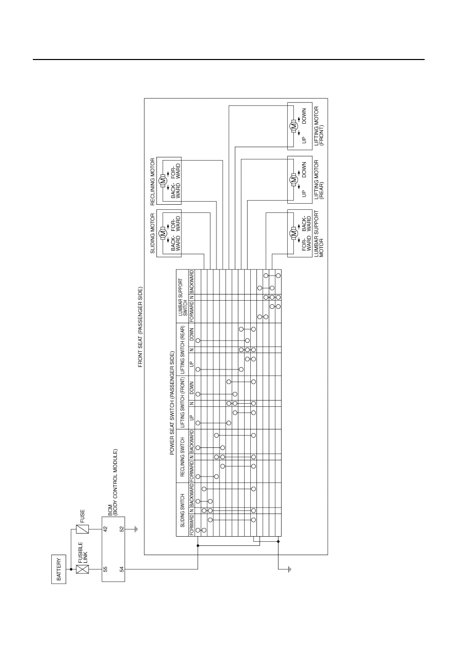
POWER SEAT(PASSENGER SIDE)
PFP:87050
Schematic
NIS0028P
TIWT2055E
Нет комментариевНе стесняйтесь поделиться с нами вашим ценным мнением.
Текст