Infiniti M35/M45 Y50. Manual — part 146
HEATER & COOLING UNIT ASSEMBLY
ATC-135
C
D
E
F
G
H
I
K
L
M
A
B
ATC
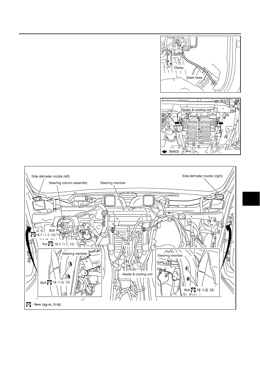
11. Disconnect drain hose.
12. Remove mounting bolts from heater & cooling unit.
13. Remove side defroster nozzles.
14. Remove steering column assembly mounting bolts and nut.
15. Remove steering member mounting bolts.
16. Remove steering member, and then remove heater & cooling unit.
INSTALLATION
Installation is basically the reverse order of removal.
RJIA4180E
RJIA4120E
SJIA1795E
ATC-136
HEATER & COOLING UNIT ASSEMBLY
CAUTION:
●
Replace O-rings of low-pressure flexible hose and high-pressure pipe 1 with new ones, and then
apply compressor oil to it when installing it.
●
Female-side piping connection is thin and easy to deform. Slowly insert the male-side piping
straight in axial direction.
●
Insert piping securely until a click is heard.
●
After piping connection is completed, pull male-side piping by hand to make sure that connection
does not come loose.
●
When recharging refrigerant, check for leaks.
NOTE:
●
When filling radiator with coolant, refer to
CO-11, "Changing Engine Coolant"
(VK45DE).
●
Recharge the refrigerant.
Heater & cooling unit assembly mounting bolt
: 6.9 N·m (0.7 kg-m, 61 in-lb)
Instrument stay mounting nut and bolt
: 12 N·m (1.25 kg-m, 9 ft-lb)
HEATER & COOLING UNIT ASSEMBLY
ATC-137
C
D
E
F
G
H
I
K
L
M
A
B
ATC
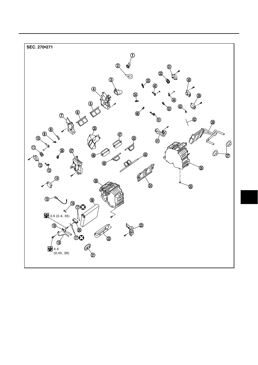
Disassembly and Assembly
NJS000HG
1.
Aspirator
2.
Aspirator hose
3.
Front heater duct (left)
4.
Foot duct (left)
5.
Ventilator door (left)
6.
Ventilator door (right)
7.
Foot duct (right)
8.
Main link sub (right)
9.
Ventilator door lever (right)
10.
Ventilator door link (right)
11.
Main link (right)
12.
Mode door motor (passenger side)
13.
Max. cool door link (right)
14.
Air mix door motor (passenger side)
15.
Intake sensor
16.
Intake sensor bracket
17.
O-ring
18.
Low-pressure pipe 1
19.
High-pressure pipe 2
20.
Expansion valve
21.
Cooler pipe grommet
22.
Insulator
23.
Evaporator cover adapter
24.
Air mix door (Slide door)
25.
Clip
26.
Heater & cooling unit case (left)
27.
Heater pipe grommet
28.
Heater core
29.
Upper ventilator door motor
30.
Air mix door motor (driver side)
31.
Mode door motor (driver side)
32.
Main link (left)
33.
Main link sub (left)
34.
Ventilator door lever (left)
35.
Center case
36.
Max. cool door lever (right)
SJIA1772E

ATC-138
HEATER & COOLING UNIT ASSEMBLY
37.
Evaporator cover
38.
Evaporator
39.
Heater & cooling unit case (right)
40.
Upper ventilator door
41.
Heater pipe cover
42.
Upper ventilator door rod
43.
Upper ventilator door lever
44.
Defroster door link
45.
Ventilator door link (left)
46.
Max. cool door lever (left)
47.
Max. cool door (left)
48.
Max. cool door (right)
49.
Defroster door (right)
50.
Defroster door (left)
51.
Max. cool door link (left)
52.
Defroster door lever
: N·m (kg-m, in-lb)
: Always replace after every disassembly.
Нет комментариевНе стесняйтесь поделиться с нами вашим ценным мнением.
Текст