Infiniti M35/M45 Y50. Manual — part 144
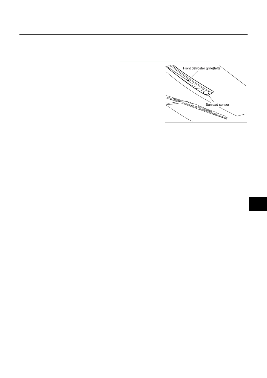
SUNLOAD SENSOR
ATC-127
C
D
E
F
G
H
I
K
L
M
A
B
ATC
SUNLOAD SENSOR
PFP:27721
Removal and Installation
NJS000H8
REMOVAL
1.
Remove front defroster grille (left). Refer to
IP-10, "INSTRUMENT PANEL ASSEMBLY"
.
2.
Disconnect sunload sensor connector, and then remove sunload
sensor.
INSTALLATION
Installation is basically the reverse order of removal.
RJIA4110E
ATC-128
INTAKE SENSOR
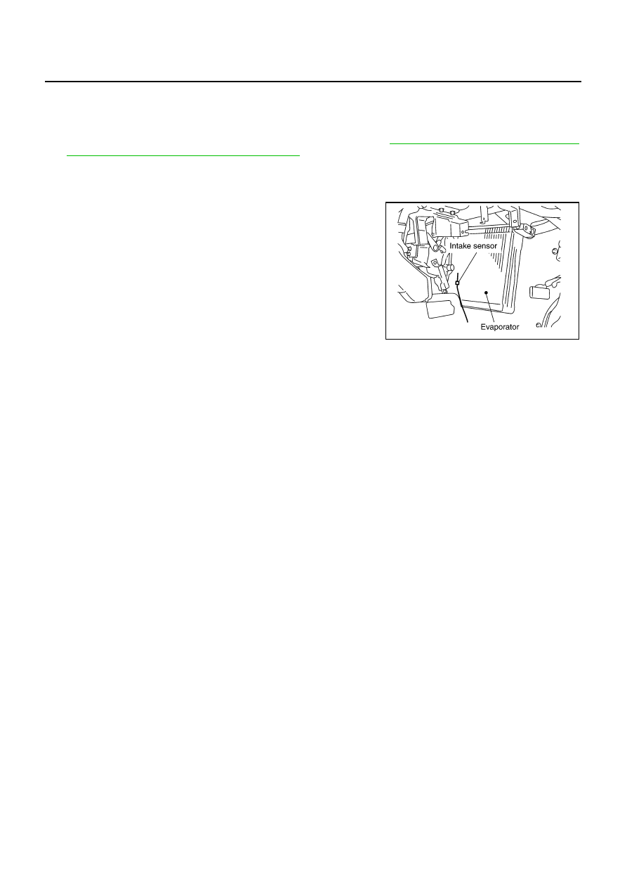
INTAKE SENSOR
PFP:27723
Removal and Installation
NJS000H9
REMOVAL
1.
Remove low-pressure pipe 1 and high-pressure pipe 2. Refer to
ATC-161, "Removal and Installation of
Low-pressure Pipe 1 and High-pressure Pipe 2"
CAUTION:
Cap or wrap the joint of evaporator, low-pressure flexible hose and high-pressure pipe 1 with suit-
able material such as vinyl tape to avoid the entry of air.
2.
Slide evaporator to passenger side, and then remove intake
sensor.
INSTALLATION
Installation is basically the reverse order of removal.
CAUTION:
●
Replace O-rings of low-pressure flexible hose, low-pressure pipe 1 and high-pressure pipe 1, 2
with new ones, and then apply compressor oil to it when installing it.
●
Mark the mounting position of intake sensor bracket prior to removal so that the reinstalled sen-
sor can be located in the same position.
●
Female-side piping connection is thin and easy to deform. Slowly insert the male-side piping
straight in axial direction.
●
Insert piping securely until a click is heard.
●
After piping connection is completed, pull male-side piping by hand to make sure that connection
does not come loose.
●
When recharging refrigerant, check for leaks.
RJIA4103E
BLOWER UNIT
ATC-129
C
D
E
F
G
H
I
K
L
M
A
B
ATC
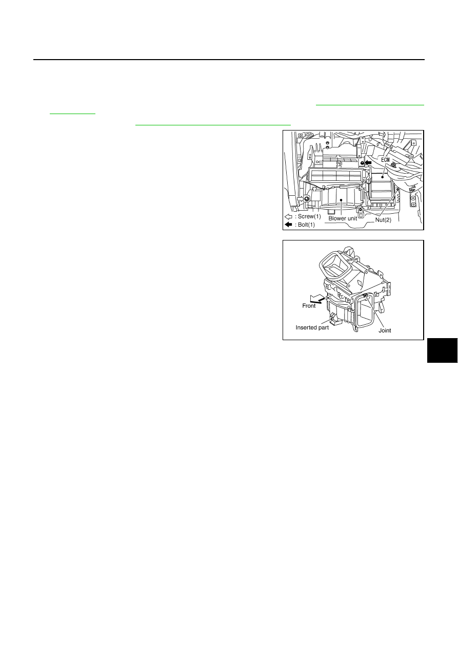
BLOWER UNIT
PFP:27200
Removal and Installation
NJS000IA
REMOVAL
1.
Remove instrument passenger lower cover and glove box cover. Refer to
.
2.
Remove BCM. Refer to
BCS-15, "Removal and Installation of BCM"
.
3.
Remove mounting nuts, and then remove ECM with bracket
attached.
4.
Disconnect intake door motor connector and blower fan motor
connector.
5.
Remove mounting bolt and screw from blower unit.
CAUTION:
Move blower unit rightward, and remove locating pin (1
part) and joint. Then remove blower unit downward.
6.
Remove blower unit.
INSTALLATION
Installation is basically the reverse order of removal.
CAUTION:
Make sure locating pin (1 part) and joint are securely inserted.
RJIA4111E
RJIA4112E
ATC-130
BLOWER UNIT
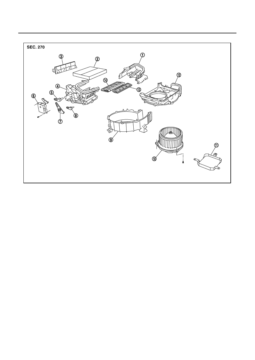
Disassembly and Assembly
NJS000IB
1.
Intake box (left)
2.
In-cabin microfilter
3.
Filter cover
4.
Intake box (right)
5.
Intake door lever 2
6.
Intake door motor
7.
Intake door link
8.
Intake door lever 1
9.
Intake lower case
10. Blower motor assembly
11.
Motor cover
12. Intake upper case
13. Intake door 1
14.
Intake door 2
SJIA1786E
Нет комментариевНе стесняйтесь поделиться с нами вашим ценным мнением.
Текст