Infiniti M35/M45 Y50. Manual — part 626
DTC P0133, P0153 A/F SENSOR 1
EC-977
[VK45DE]
C
D
E
F
G
H
I
J
K
L
M
A
EC
●
Intake air leaks
●
Exhaust gas leaks
●
Incorrect fuel pressure
●
Lack of fuel
●
Fuel injector
●
Incorrect PCV hose connection
●
PCV valve
●
Mass air flow sensor
4.
Turn ignition switch OFF and wait at least 10 seconds.
5.
Start engine and keep the engine speed between 3,500 and 4,000 rpm for at least 1minute under no load.
6.
Let engine idle for 1 minute.
7.
Increase the engine speed up to 4,000 to 5,000 rpm and keep it for 10 seconds.
8.
Fully release accelerator pedal and then let engine idle for about 1 minute.
9.
Select Service $07 with GST.
If the 1st trip DTC is displayed, go to
EC-978
[VK45DE]
DTC P0133, P0153 A/F SENSOR 1
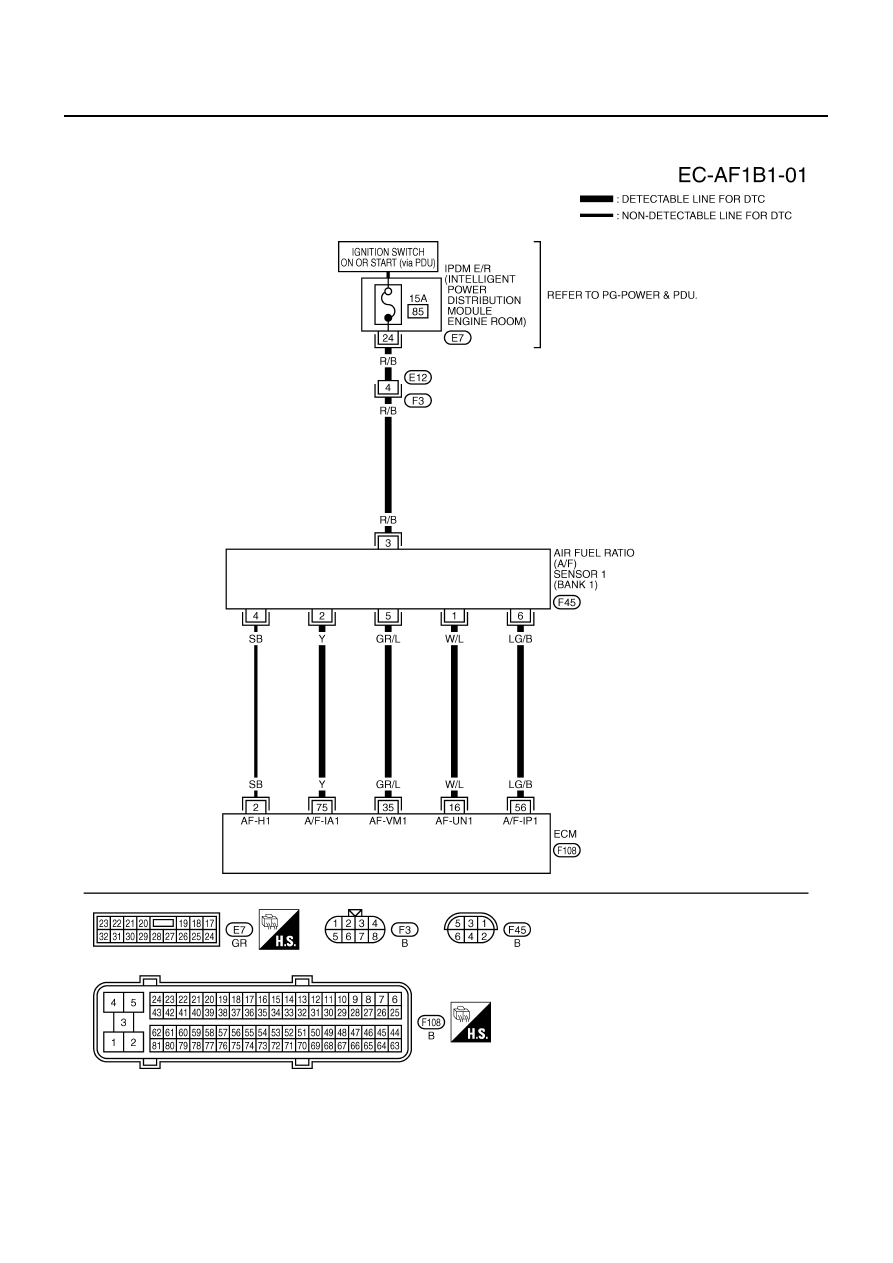
Wiring Diagram
NBS005EF
BANK 1
TBWT1046E
DTC P0133, P0153 A/F SENSOR 1
EC-979
[VK45DE]
C
D
E
F
G
H
I
J
K
L
M
A
EC
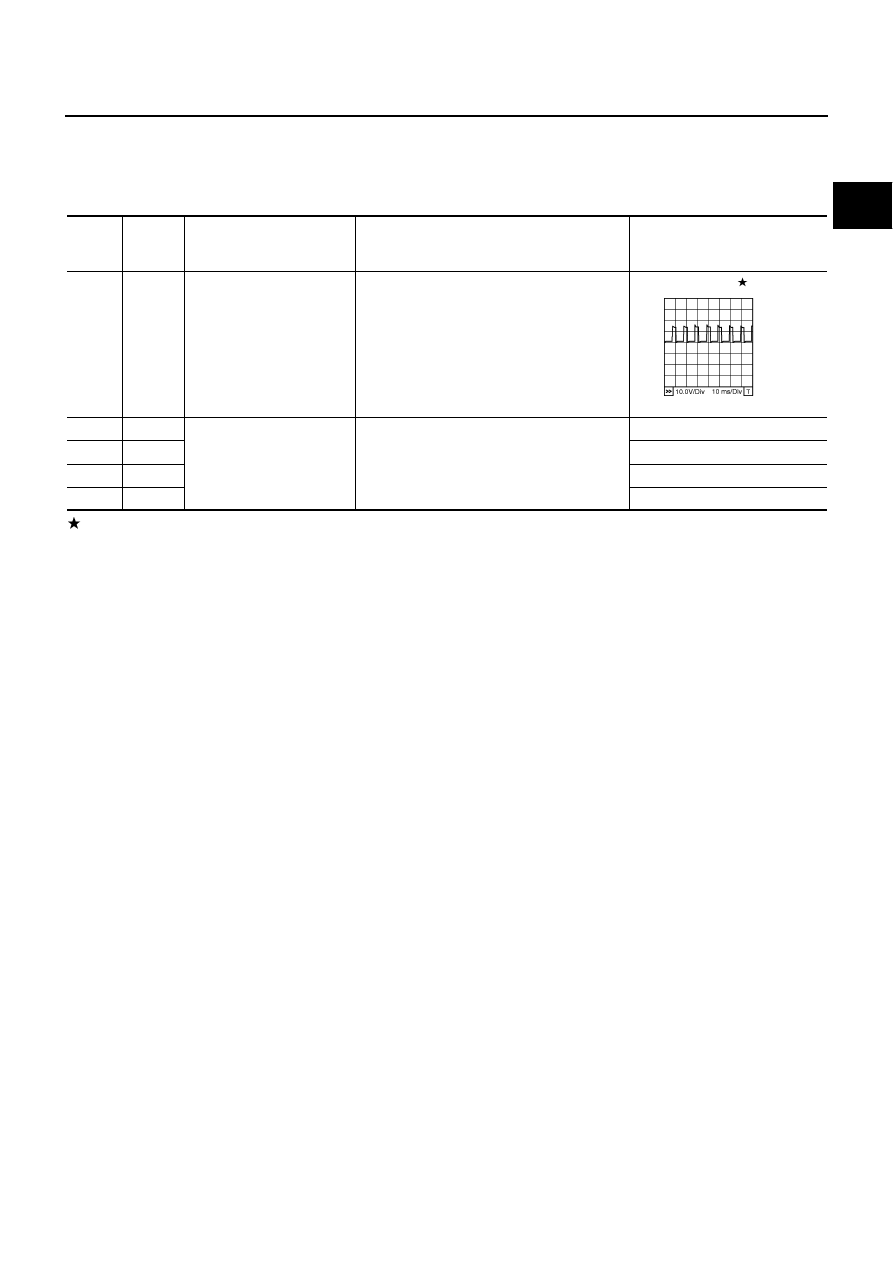
Specification data are reference values and are measured between each terminal and ground.
Pulse signal is measured by CONSULT-II.
CAUTION:
Do not use ECM ground terminals when measuring input/output voltage. Doing so may result in dam-
age to the ECM's transistor. Use a ground other than ECM terminals, such as the ground.
: Average voltage for pulse signal (Actual pulse signal can be confirmed by oscilloscope.)
TER-
MINAL
NO.
WIRE
COLOR
ITEM
CONDITION
DATA (DC Voltage)
2
SB
A/F sensor 1 heater
(bank 1)
[Engine is running]
●
Warm-up condition
●
Idle speed
Approximately 5V
16
W/L
A/F sensor 1 (bank 1)
[Engine is running]
●
Warm-up condition
●
Idle speed
Approximately 3.1V
35
GR/L
Approximately 2.6V
56
LG/B
Approximately 2.3V
75
Y
Approximately 2.3V
PBIB1584E
EC-980
[VK45DE]
DTC P0133, P0153 A/F SENSOR 1
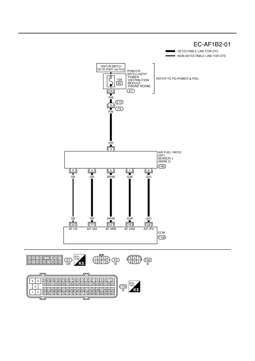
BANK 2
TBWT1047E
Нет комментариевНе стесняйтесь поделиться с нами вашим ценным мнением.
Текст