Infiniti M35/M45 Y50. Manual — part 625

DTC P0132, P0152 A/F SENSOR 1
EC-973
[VK45DE]
C
D
E
F
G
H
I
J
K
L
M
A
EC
4.
CHECK A/F SENSOR 1 INPUT SIGNAL CIRCUIT FOR OPEN AND SHORT
1.
Turn ignition switch OFF.
2.
Disconnect ECM harness connector.
3.
Check harness continuity between A/F sensor 1 terminal and ECM terminal as follows.
Refer to Wiring Diagram.
4.
Check harness continuity between the following terminals and ground.
Refer to Wiring Diagram.
5.
Also check harness for short to power.
OK or NG
OK
>> GO TO 5.
NG
>> Repair open circuit or short to ground or short to power in harness or connectors.
5.
CHECK INTERMITTENT INCIDENT
Perform
EC-857, "TROUBLE DIAGNOSIS FOR INTERMITTENT INCIDENT"
OK or NG
OK
>> GO TO 6.
NG
>> Repair or replace.
6.
REPLACE AIR FUEL RATIO (A/F) SENSOR 1
Replace malfunctioning air fuel ratio (A/F) sensor 1.
CAUTION:
●
Discard any A/F sensor which has been dropped from a height of more than 0.5 m (19.7 in) onto a
hard surface such as a concrete floor; use a new one.
●
Before installing new A/F sensor, clean exhaust system threads using Oxygen Sensor Thread
Cleaner tool J-43897-18 or J-43897-12 and approved anti-seize lubricant.
>> INSPECTION END
A/F sensor 1 terminal
ECM terminal
Bank1
1
16
2
75
5
35
6
56
Bank 2
1
76
2
77
5
57
6
58
Continuity should exist.
Bank 1
Bank 2
A/F sensor 1 terminal
ECM terminal
A/F sensor 1 terminal
ECM terminal
1
16
1
76
2
75
2
77
5
35
5
57
6
56
6
58
Continuity should not exist.
EC-974
[VK45DE]
DTC P0132, P0152 A/F SENSOR 1
Removal and Installation
NBS005EA
AIR FUEL RATIO (A/F) SENSOR 1
Refer to
DTC P0133, P0153 A/F SENSOR 1
EC-975
[VK45DE]
C
D
E
F
G
H
I
J
K
L
M
A
EC
DTC P0133, P0153 A/F SENSOR 1
PFP:22693
Component Description
NBS005EB
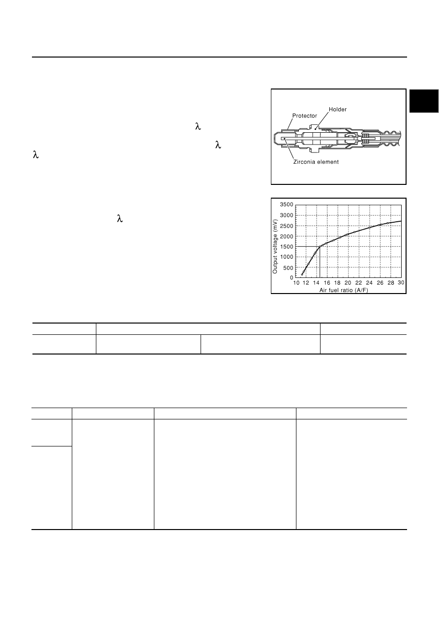
The air fuel ratio (A/F) sensor 1 is a planar dual-cell limit current sen-
sor. The sensor element of the A/F sensor 1 is the combination of a
Nernst concentration cell (sensor cell) with an oxygen-pump cell,
which transports ions. It has a heater in the element.
The sensor is capable of precise measurement = 1, but also in the
lean and rich range. Together with its control electronics, the sensor
outputs a clear, continuous signal throughout a wide range (0.7 <
< air).
The exhaust gas components diffuse through the diffusion gap at the
electrode of the oxygen pump and Nernst concentration cell, where
they are brought to thermodynamic balance.
An electronic circuit controls the pump current through the oxygen-
pump cell so that the composition of the exhaust gas in the diffusion
gap remains constant at = 1. Therefore, the A/F sensor 1 is able to
indicate air/fuel ratio by this pumping of current. In addition, a heater
is integrated in the sensor to ensure the required operating tempera-
ture of 700 - 800
°
C (1,292 - 1,472
°
F).
CONSULT-II Reference Value in Data Monitor Mode
NBS005EC
Specification data are reference values.
On Board Diagnosis Logic
NBS005ED
To judge the malfunction of A/F sensor 1, this diagnosis measures response time of the A/F signal computed
by ECM from the A/F sensor 1 signal. The time is compensated by engine operating (speed and load), fuel
feedback control constant, and the A/F sensor 1 temperature index. Judgment is based on whether the com-
pensated time (the A/F signal cycling time index) is inordinately long or not.
SEF579Z
SEF580Z
MONITOR ITEM
CONDITION
SPECIFICATION
A/F SEN1 (B1)
A/F SEN1 (B2)
●
Engine: After warming up
Maintaining engine speed at 2,000 rpm
Fluctuates around 1.5 V
DTC No.
Trouble diagnosis name
DTC detecting condition
Possible Cause
P0133
0133
(Bank 1)
Air fuel ratio (A/F) sensor 1
circuit slow response
●
The response of the A/F signal computed by
ECM from A/F sensor 1 signal takes more than
the specified time.
●
Harness or connectors
(The A/F sensor 1 circuit is open or
shorted.)
●
A/F sensor 1
●
A/F sensor 1 heater
●
Fuel pressure
●
Fuel injector
●
Intake air leaks
●
Exhaust gas leaks
●
PCV
●
Mass air flow sensor
P0153
0153
(Bank 2)
EC-976
[VK45DE]
DTC P0133, P0153 A/F SENSOR 1
DTC Confirmation Procedure
NBS005EE
NOTE:
If DTC Confirmation Procedure has been previously conducted, always turn ignition switch OFF and wait at
least 10 seconds before conducting the next test.
TESTING CONDITION:
Before performing the following procedure, confirm that battery voltage is more than 11V at idle.
WITH CONSULT-II
1.
Start engine and warm it up to normal operating temperature.
2.
Turn ignition switch OFF and wait at least 10 seconds.
3.
Start engine and keep the engine speed between 3,500 and 4,000 rpm for at least 1minute under no load.
4.
Let engine idle for 1 minute.
5.
Select “A/F SEN1(B1) P1278/P1279” (for DTC P0133) or “A/F SEN1(B1) P1288/P1289” (for DTC P0153)
of “A/F SEN1” in “DTC WORK SUPPORT” mode with CONSULT-II.
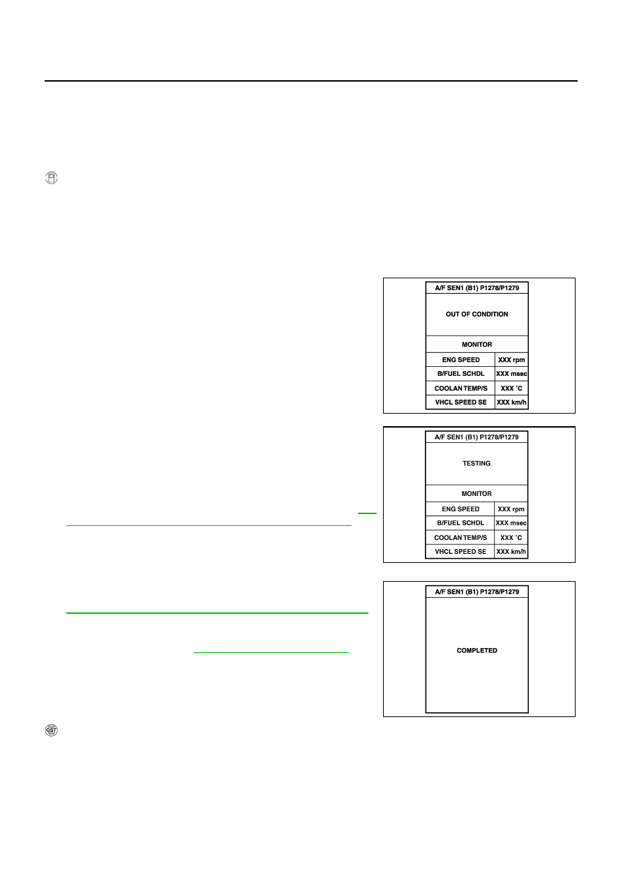
6.
Touch “START”.
If “COMPLETED” appears on CONSULT-II screen, go to step
10.
If “COMPLETED” does not appear on CONSULT-II screen, go to
the following step.
7.
After perform the following procedure, “TESTING” will be dis-
played on the CONSULT-II screen.
a.
Increase the engine speed up to 4,000 to 5,000 rpm and keep it
for 10 seconds.
b.
Fully release accelerator pedal and then let engine idle for about
10 seconds.
If “TESTING” is not displayed after 10 seconds, refer to
847, "TROUBLE DIAGNOSIS - SPECIFICATION VALUE"
8.
Wait for about 20 seconds at idle at under the condition that
“TESTING” is displayed on the CONSULT-II screen.
9.
Make sure that “TESTING” changes to “COMPLETED”.
If “TESTING” changed to “OUT OF CONDITION”, refer to
EC-847, "TROUBLE DIAGNOSIS - SPECIFICATION VALUE"
10. Make sure that “OK” is displayed after touching “SELF-DIAG
RESULT”.
If “NG” is displayed, go to
EC-981, "Diagnostic Procedure"
WITH GST
1.
Start engine and warm it up to normal operating temperature.
2.
Select Service $01 with GST.
3.
Calculate the total value of “Short term fuel trim” and “Long term fuel trim” indications.
Make sure that the total percentage should be within
±
15%.
If OK, go to the following step.
If NG, check the following.
PBIB0756E
PBIB1925E
PBIB0758E
Нет комментариевНе стесняйтесь поделиться с нами вашим ценным мнением.
Текст