Infiniti M35/M45 Y50. Manual — part 559

SNOW MODE SWITCH
EC-709
[VQ35DE]
C
D
E
F
G
H
I
J
K
L
M
A
EC
SNOW MODE SWITCH
PFP:25310
Description
NBS0058Q
NOTE:
If DTC U1000 or U1001 are displayed, first perform the trouble diagnosis for DTC U1000, U1001.
Refer to
EC-161, "DTC U1000, U1001 CAN COMMUNICATION LINE"
If DTC U1010 is displayed, first perform the trouble diagnosis for DTC U1010.
Refer to
EC-164, "DTC U1010 CAN COMMUNICATION"
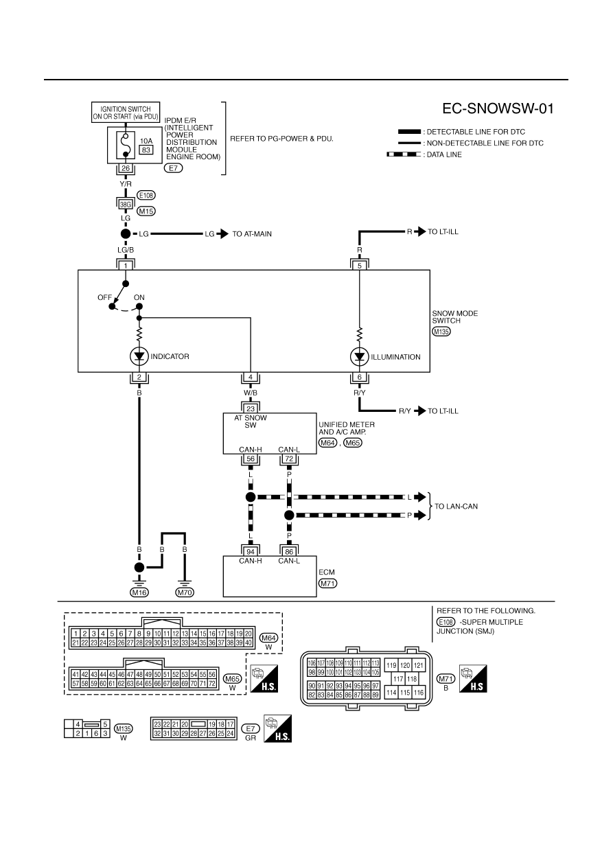
The snow mode switch signal is sent to the “unified meter and A/C amp.” from the snow mode switch. The
“unified meter and A/C amp.” then sends the signal to the ECM by CAN communication line.
The snow mode is used for driving or starting the vehicle on snowy roads or slippery areas. If the snow mode
is activated, the vehicle speed will not be accelerated immediately than your original pedal in due to avoid the
vehicle slip. In other words, ECM controls the rapid engine torque change by controlling the electric throttle
control actuator operating speed.
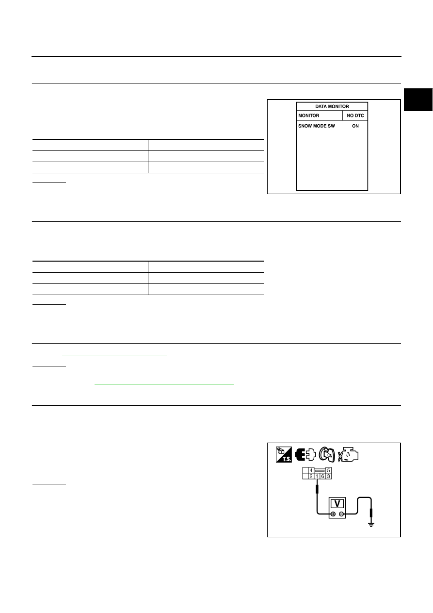
CONSULT-II Reference Value in the Data Monitor Mode
NBS0058R
MONITOR ITEM
CONDITION
SPECIFICATION
SNOW MODE SW
●
Ignition switch: ON
SNOW MODE SW: ON
ON
SNOW MODE SW: OFF
OFF
EC-710
[VQ35DE]
SNOW MODE SWITCH
Wiring Diagram
NBS0058S
TBWT1003E
SNOW MODE SWITCH
EC-711
[VQ35DE]
C
D
E
F
G
H
I
J
K
L
M
A
EC
Diagnostic Procedure
NBS0058T
1.
CHECK SNOW MODE SWITICH OVERALL FUNCTION-I
1.
Turn ignition switch ON.
2.
Select “SNOW MODE SW” in “DATA MONITOR” mode with
CONSULT-II.
3.
Check “SNOW MODE SW” indication under the following condi-
tions.
OK or NG
OK
>> GO TO 2.
NG
>> GO TO 3.
2.
CHECK SNOW MODE SWITICH OVERALL FUNCTION-II
1.
Turn ignition switch ON.
2.
Start engine.
3.
Check the snow mode indicator in the snow mode switch under the following condition.
OK or NG
OK
>> INSPECTION END
NG
>> GO TO 7.
3.
CHECK DTC WITH “UNIFIED METER AND A/C AMP.”
Refer to
OK or NG
OK
>> GO TO 4.
NG
DI-28, "UNIFIED METER AND A/C AMP"
.
4.
CHECK SNOW MODE SWITCH POWER SUPPLY CIRCUIT
1.
Turn ignition switch OFF.
2.
Disconnect snow mode switch harness connector.
3.
Turn ignition switch ON.
4.
Check voltage between snow mode switch terminal 1 and
ground with CONSULT-II or tester.
OK or NG
OK
>> GO TO 6.
NG
>> GO TO 5.
CONDITION
INDICATION
Snow mode switch: ON
ON
Snow mode switch: OFF
OFF
PBIB2009E
CONDITION
INDICATION
Snow mode switch: ON
ON
Snow mode switch: OFF
OFF
Voltage: Battery voltage.
PBIB2562E
EC-712
[VQ35DE]
SNOW MODE SWITCH
5.
DETECT MALFUNCTIONING PART
Check the following.
●
Harness connectors E108, M15
●
IPDM E/R harness connector E7
●
10A fuse
●
Harness for open or short between snow mode switch and fuse.
>> Repair open circuit or short to ground or short to power in harness or connectors.
6.
CHECK SNOW MODE SWITCH INPUT SIGNAL CIRCUIT FOR OPEN AND SHORT
1.
Turn ignition switch OFF.
2.
Disconnect “unified meter and A/C amp.” harness connector.
3.
Check harness continuity between snow mode switch terminal 4 and “unified meter and A/C amp.” termi-
nal 23. Refer to Wiring Diagram.
4.
Also check harness for short to ground and short to power.
OK or NG
OK
>> GO TO 9.
NG
>> Repair open circuit or short to ground or short to power in harness or connectors.
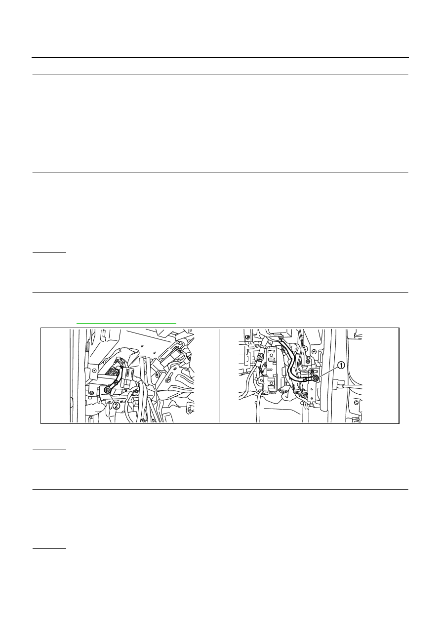
7.
CHECK GROUND CONNECTIONS
1.
Turn ignition switch OFF.
2.
Loosen and retighten two ground screws on the body.
Refer to
OK or NG
OK
>> GO TO 8.
NG
>> Repair or replace ground connections.
8.
CHECK SNOW MODE INDICATOR LAMP GROUND CIRCUIT FOR OPEN AND SHORT
1.
Check harness continuity between snow mode switch terminal 2 and ground.
Refer to Wiring Diagram.
2.
Also check harness for short to power.
OK or NG
OK
>> GO TO 9.
NG
>> Repair open circuit or short to power in harness or connectors.
Continuity should exist.
1.
Body ground M70
2.
Body ground M16
PBIB2782E
Continuity should exist.
Нет комментариевНе стесняйтесь поделиться с нами вашим ценным мнением.
Текст