Infiniti M35/M45 Y50. Manual — part 758

EXHAUST SYSTEM
EX-5
C
D
E
F
G
H
I
J
K
L
M
A
EX
Removal and Installation
NBS005RL
CAUTION:
●
Be sure to use genuine exhaust system parts or equivalents which are specially designed for heat
resistance, corrosion resistance, and shape.
●
Perform the operation with the exhaust system fully cooled down because the system will be hot
just after engine stops.
●
Be careful not to cut your hand on the heat insulator edge.
REMOVAL
●
Disconnect each joint and mounting using power tool.
●
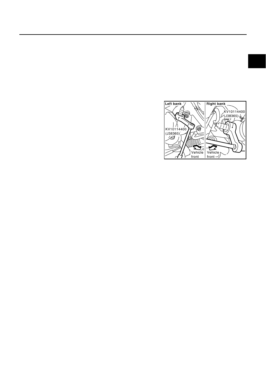
Remove heated oxygen sensor 2 as follows:
–
Using heated oxygen sensor wrench (SST), removal heated
oxygen sensor 2.
CAUTION:
Be careful not to damage heated oxygen sensor 2.
INSTALLATION
Note the following, and install in the reverse order of removal.
●
Check for deformation of the grommets (18 and 20 of Components).
●
Insert the collar (17 of Components) vertically.
●
Install the collar (5 of Components) with its lower surface horizontal.
●
Temporarily tighten nuts and bolts when installing exhaust pipe assembly. Tighten them to the specified
torque when connecting the vehicle rear to the vehicle front.
CAUTION:
●
Always replace exhaust tube gaskets with new ones when reassembling.
●
Discard any heated oxygen sensor which has been dropped onto a hard surface such as a con-
crete floor. Use a new one.
●
Before installing a new heated oxygen sensor, clean exhaust system threads using the heated
oxygen sensor thread cleaner [commercial service tool: J-43897-18 or J-43897-12], and apply the
anti-seize lubricant (commercial service tool).
●
Do not over torque heated oxygen sensor. Doing so may cause damage to heated oxygen sensor,
resulting in the “MIL” coming on.
●
If heat insulator is badly deformed, repair or replace it. If deposits such as mud pile up on the heat
insulator, remove them.
●
When installing heat insulator avoid large gaps or interference between heat insulator and each
exhaust pipe.
●
Remove deposits from the sealing surface of each connection. Connect them securely to avoid
gases leakage.
●
Temporarily tighten mounting nuts on the exhaust manifold side and mounting bolts on the vehi-
cle side. Check each part for unusual interference, and then tighten them to the specified torque.
●
When installing each mounting rubber, avoid twisting or unusual extension in up/down and right/
left directions.
INSPECTION AFTER INSTALLATION
●
Make sure clearance between tail tube and rear bumper is even.
●
With engine running, check exhaust tube joints for gas leakage and unusual noises.
●
Check to ensure that mounting brackets and mounting rubbers are installed properly and free from undue
stress. Improper installation could result in excessive noise and vibration.
PBIC2298E
EX-6
EXHAUST SYSTEM
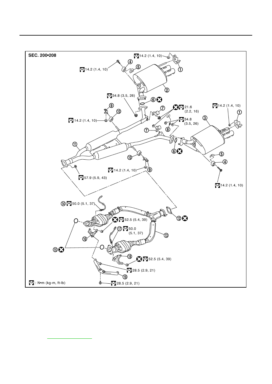
Components
NBS005RM
VK45DE
●
Refer to
for symbols in the figure.
PBIC3307E
1.
Mounting bracket
2.
Main muffler (RH)
3.
Main muffler (LH)
4.
Mounting rubber
5.
Collar
6.
Ring gasket
7.
Dynamic damper
8.
Wire bonding
9.
Mounting bracket
10. Mounting rubber
11. Center muffler
12. Gasket
13. Exhaust front tube
14. Heated oxygen sensor 2 (bank 2)
15. Ring gasket
16. Mounting bracket
17. Heated oxygen sensor 2 (bank 1)
18. Mounting bracket
19. Exhaust mounting bracket
EXHAUST SYSTEM
EX-7
C
D
E
F
G
H
I
J
K
L
M
A
EX
Removal and installation
NBS005RN
CAUTION:
●
Be sure to use genuine exhaust system parts or equivalents which are specially designed for heat
resistance, corrosion resistance, and shape.
●
Perform the operation with the exhaust system fully cooled down because the system will be hot
just after engine stops.
●
Be careful not to cut your hand on the heat insulator edge.
REMOVAL
●
Disconnect each joint and mounting using power tool.
●
Remove heated oxygen sensor 2 as follows:
–
Using heated oxygen sensor wrench (SST), removal heated
oxygen sensor 2.
CAUTION:
Be careful not to damage heated oxygen sensor 2.
INSTALLATION
Note the following, and install in the reverse order of removal.
●
Install the collar (5 of Components) with its lower surface horizontal.
●
Temporarily tighten nuts and bolts when installing exhaust pipe assembly. Tighten them to the specified
torque when connecting the vehicle rear to the vehicle front.
CAUTION:
●
Always replace exhaust tube gaskets with new ones when reassembling.
●
Discard any heated oxygen sensor which has been dropped onto a hard surface such as a con-
crete floor. Use a new one.
●
Before installing a new heated oxygen sensor, clean exhaust system threads using the heated
oxygen sensor thread cleaner [commercial service tool: J-43897-18 or J-43897-12], and apply the
anti-seize lubricant (commercial service tool).
●
Do not over torque heated oxygen sensor. Doing so may cause damage to heated oxygen sensor,
resulting in the “MIL” coming on.
●
If heat insulator is badly deformed, repair or replace it. If deposits such as mud pile up on the heat
insulator, remove them.
●
When installing heat insulator avoid large gaps or interference between heat insulator and each
exhaust pipe.
●
Remove deposits from the sealing surface of each connection. Connect them securely to avoid
gases leakage.
●
Check each part for unusual interference, and then tighten them to the specified torque.
●
When installing each mounting rubber, avoid twisting or unusual extension in up/down and right/
left directions.
INSPECTION AFTER INSTALLATION
●
Make sure clearance between tail tube and rear bumper is even.
●
With engine running, check exhaust tube joints for gas leakage and unusual noises.
●
Check to ensure that mounting brackets and mounting rubbers are installed properly and free from undue
stress. Improper installation could result in excessive noise and vibration.
PBIC2334E
EX-8
EXHAUST SYSTEM
Нет комментариевНе стесняйтесь поделиться с нами вашим ценным мнением.
Текст