Infiniti M35/M45 Y50. Manual — part 610
DTC P0101 MAF SENSOR
EC-913
[VK45DE]
C
D
E
F
G
H
I
J
K
L
M
A
EC
Component Inspection
NBS005CC
MASS AIR FLOW SENSOR
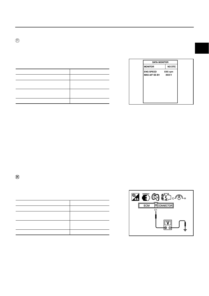
With CONSULT-II
1.
Reconnect all harness connectors disconnected.
2.
Start engine and warm it up to normal operating temperature.
3.
Connect CONSULT-II and select “DATA MONITOR” mode.
4.
Select “MAS A/F SE-B1” and check indication under the follow-
ing conditions.
*: Check for linear voltage rise in response to engine being increased to about
4,000 rpm.
5.
If the voltage is out of specification, proceed the following.
a.
Check for the cause of uneven air flow through mass air flow sensor. Refer to following.
●
Crushed air ducts
●
Malfunctioning seal of air cleaner element
●
Uneven dirt of air cleaner element
●
Improper specification of intake air system parts
b.
If NG, repair or replace malfunctioning part and perform step 2 to 4 again.
If OK, go to next step.
6.
Turn ignition switch OFF.
7.
Disconnect mass air flow sensor harness connector and reconnect it again.
8.
Perform step 2 to 4 again.
9.
If NG, clean or replace mass air flow sensor.
Without CONSULT-II
1.
Reconnect all harness connectors disconnected.
2.
Start engine and warm it up to normal operating temperature.
3.
Check voltage between ECM terminal 51 (Mass air flow sensor
signal) and ground.
*: Check for linear voltage rise in response to engine being increased to about
4,000 rpm.
4.
If the voltage is out of specification, proceed the following.
a.
Check for the cause of uneven air flow through mass air flow sensor. Refer to following.
●
Crushed air ducts
●
Malfunctioning seal of air cleaner element
●
Uneven dirt of air cleaner element
●
Improper specification of intake air system parts
Condition
MAS A/F SE-B1 (V)
Ignition switch ON (Engine stopped.)
Approx. 0.4
Idle (Engine is warmed-up to normal
operating temperature.)
0.9 - 1.2
2,500 rpm (Engine is warmed-up to
normal operating temperature.)
1.6 - 1.9
Idle to about 4,000 rpm
0.9 - 1.2 to Approx. 2.4*
PBIB2371E
Condition
Voltage V
Ignition switch ON (Engine stopped.)
Approx. 0.4
Idle (Engine is warmed-up to normal
operating temperature.)
0.9 - 1.2
2,500 rpm (Engine is warmed-up to
normal operating temperature.)
1.6 - 1.9
Idle to about 4,000 rpm
0.9 - 1.2 to Approx. 2.4*
PBIB1106E
EC-914
[VK45DE]
DTC P0101 MAF SENSOR
b.
If NG, repair or replace malfunctioning part and perform step 2 to 3 again.
If OK, go to next step.
5.
Turn ignition switch OFF.
6.
Disconnect mass air flow sensor harness connector and reconnect it again.
7.
Perform step 2 and 3 again.
8.
If NG, clean or replace mass air flow sensor.
Removal and Installation
NBS005CD
MASS AIR FLOW SENSOR
Refer to
DTC P0102, P0103 MAF SENSOR
EC-915
[VK45DE]
C
D
E
F
G
H
I
J
K
L
M
A
EC
DTC P0102, P0103 MAF SENSOR
PFP:22680
Component Description
NBS005CE
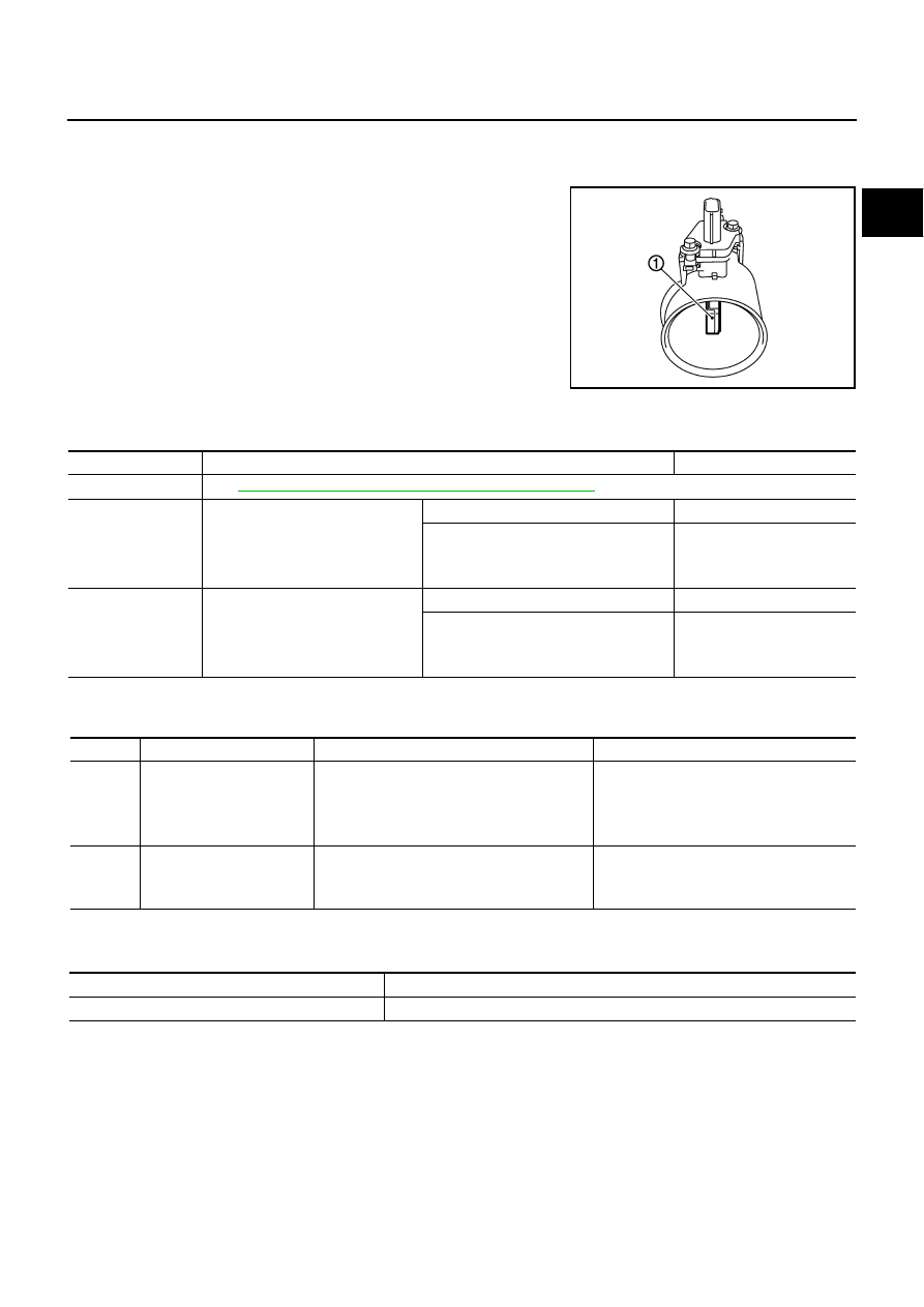
The mass air flow sensor (1) is placed in the stream of intake air. It
measures the intake flow rate by measuring a part of the entire
intake flow. The mass air flow sensor controls the temperature of the
hot wire to a certain amount. The heat generated by the hot wire is
reduced as the intake air flows around it. The more air, the greater
the heat loss.
Therefore, the electric current supplied to hot wire is changed to
maintain the temperature of the hot wire as air flow increases. The
ECM detects the air flow by means of this current change.
CONSULT-II Reference Value in Data Monitor Mode
NBS005CF
Specification data are reference values.
On Board Diagnosis Logic
NBS005CG
These self-diagnoses have the one trip detection logic.
FAIL-SAFE MODE
When the malfunction is detected, the ECM enters fail-safe mode and the MIL lights up.
PBIA9559J
MONITOR ITEM
CONDITION
SPECIFICATION
MAS A/F SE-B1
See
EC-847, "TROUBLE DIAGNOSIS - SPECIFICATION VALUE"
CAL/LD VALUE
●
Engine: After warming up
●
Selector lever: P or N
●
Air conditioner switch: OFF
●
No load
Idle
14% - 33%
2,500 rpm
12% - 25%
MASS AIRFLOW
●
Engine: After warming up
●
Selector lever: P or N
●
Air conditioner switch: OFF
●
No load
Idle
2.0 - 6.0 g·m/s
2,500 rpm
7.0 - 20.0 g·m/s
DTC No.
Trouble diagnosis name
DTC detecting condition
Possible cause
P0102
0102
Mass air flow sensor circuit
low input
An excessively low voltage from the sensor is
sent to ECM.
●
Harness or connectors
(The sensor circuit is open or shorted.)
●
Intake air leaks
●
Mass air flow sensor
P0103
0103
Mass air flow sensor circuit
high input
An excessively high voltage from the sensor is
sent to ECM.
●
Harness or connectors
(The sensor circuit is open or shorted.)
●
Mass air flow sensor
Detected items
Engine operating condition in fail-safe mode
Mass air flow sensor circuit
Engine speed will not rise more than 2,400 rpm due to the fuel cut.
EC-916
[VK45DE]
DTC P0102, P0103 MAF SENSOR
DTC Confirmation Procedure
NBS005CH
NOTE:
If DTC Confirmation Procedure has been previously conducted, always turn ignition switch OFF and wait at
least 10 seconds before conducting the next test.
PROCEDURE FOR DTC P0102
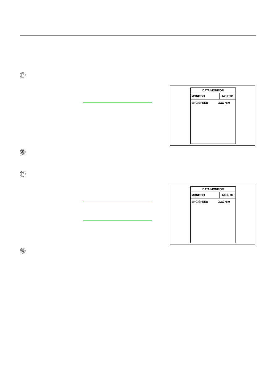
With CONSULT-II
1.
Turn ignition switch ON.
2.
Select “DATA MONITOR” mode with CONSULT-II.
3.
Start engine and wait at least 5 seconds.
4.
If DTC is detected, go to
EC-918, "Diagnostic Procedure"
.
With GST
Follow the procedure “With CONSULT-II” above.
PROCEDURE FOR DTC P0103
With CONSULT-II
1.
Turn ignition switch ON.
2.
Select “DATA MONITOR” mode with CONSULT-II.
3.
Wait at least 5 seconds.
4.
If DTC is detected, go to
EC-918, "Diagnostic Procedure"
.
If DTC is not detected, go to next step.
5.
Start engine and wait at least 5 seconds.
6.
If DTC is detected, go to
EC-918, "Diagnostic Procedure"
.
With GST
Follow the procedure “With CONSULT-II” above.
SEF058Y
SEF058Y
Нет комментариевНе стесняйтесь поделиться с нами вашим ценным мнением.
Текст