Infiniti M35/M45 Y50. Manual — part 608
DTC P0075, P0081 IVT CONTROL SOLENOID VALVE
EC-905
[VK45DE]
C
D
E
F
G
H
I
J
K
L
M
A
EC
4.
CHECK INTAKE VALVE TIMING CONTROL SOLENOID VALVE
Refer to
EC-905, "Component Inspection"
OK or NG
OK
>> GO TO 5.
NG
>> Replace intake valve timing control solenoid valve.
5.
CHECK INTERMITTENT INCIDENT
Refer to
EC-857, "TROUBLE DIAGNOSIS FOR INTERMITTENT INCIDENT"
>> INSPECTION END
Component Inspection
NBS005C3
INTAKE VALVE TIMING CONTROL SOLENOID VALVE
1.
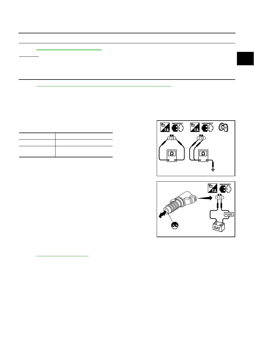
Disconnect intake valve timing control solenoid valve harness connector.
2.
Check resistance between intake valve timing control solenoid
valve terminals as follows.
If NG, replace intake valve timing control solenoid valve.
If OK, go to next step.
3.
Remove intake valve timing control solenoid valve.
4.
Provide 12V DC between intake valve timing control solenoid
valve terminals and then interrupt it. Make sure that the plunger
moves as shown in the figure.
CAUTION:
Do not apply 12V DC continuously for 5 seconds or more.
Doing so may result in damage to the coil in intake valve
timing control solenoid valve.
If NG, replace intake valve timing control solenoid valve.
NOTE:
Always replace O-ring when intake valve timing control
solenoid valve is removed.
Removal and Installation
NBS005C4
INTAKE VALVE TIMING CONTROL SOLENOID VALVE
Refer to
Terminals
Resistance
1 and 2
7.0 - 7.5
Ω
[at 20
°
C (68
°
F)]
1 or 2 and ground
∞Ω
(Continuity should not exist)
PBIB0193E
PBIB2275E
EC-906
[VK45DE]
DTC P0101 MAF SENSOR
DTC P0101 MAF SENSOR
PFP:22680
Component Description
NBS005C5
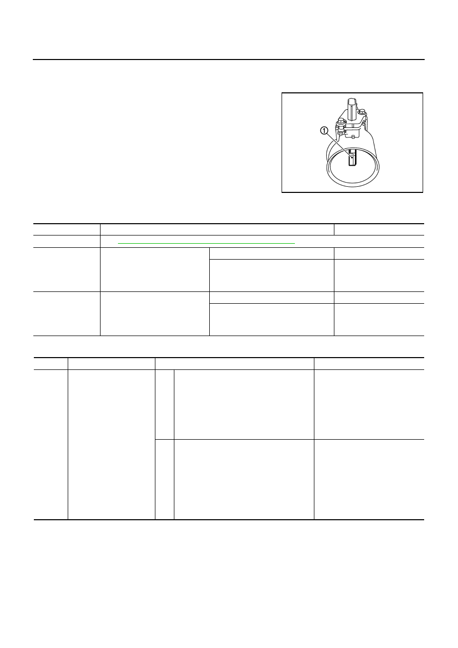
The mass air flow sensor (1) is placed in the stream of intake air. It
measures the intake flow rate by measuring a part of the entire
intake flow. The mass air flow sensor controls the temperature of the
hot wire to a certain amount. The heat generated by the hot wire is
reduced as the intake air flows around it. The more air, the greater
the heat loss.
Therefore, the electric current supplied to hot wire is changed to
maintain the temperature of the hot wire as air flow increases. The
ECM detects the air flow by means of this current change.
CONSULT-II Reference Value in Data Monitor Mode
NBS005C6
Specification data are reference values.
On Board Diagnosis Logic
NBS005C7
PBIA9559J
MONITOR ITEM
CONDITION
SPECIFICATION
MAS A/F SE-B1
See
EC-847, "TROUBLE DIAGNOSIS - SPECIFICATION VALUE"
CAL/LD VALUE
●
Engine: After warming up
●
Selector lever: P or N
●
Air conditioner switch: OFF
●
No load
Idle
14% - 33%
2,500 rpm
12% - 25%
MASS AIRFLOW
●
Engine: After warming up
●
Selector lever: P or N
●
Air conditioner switch: OFF
●
No load
Idle
2.0 - 6.0 g·m/s
2,500 rpm
7.0 - 20.0 g·m/s
DTC No.
Trouble diagnosis name
DTC detecting condition
Possible cause
P0101
0101
Mass air flow sensor circuit
range/performance
A)
A high voltage from the sensor is sent to ECM
under light load driving condition.
●
Harness or connectors
(The sensor circuit is open or
shorted.)
●
Mass air flow sensor
●
EVAP control system pressure
sensor
●
Intake air temperature sensor
B)
A low voltage from the sensor is sent to ECM
under heavy load driving condition.
●
Harness or connectors
(The sensor circuit is open or
shorted.)
●
Intake air leaks
●
Mass air flow sensor
●
EVAP control system pressure
sensor
●
Intake air temperature sensor
DTC P0101 MAF SENSOR
EC-907
[VK45DE]
C
D
E
F
G
H
I
J
K
L
M
A
EC
DTC Confirmation Procedure
NBS005C8
Perform PROCEDURE FOR MALFUNCTION A first.
If DTC cannot be confirmed, perform PROCEDURE FOR MALFUNCTION B.
NOTE:
If DTC Confirmation Procedure has been previously conducted, always turn ignition switch OFF and wait at
least 10 seconds before conducting the next test.
PROCEDURE FOR MALFUNCTION A
NOTE:
If engine will not start or stops soon, wait at least 10 seconds with engine stopped (Ignition switch ON) instead
of running engine at idle speed.
With CONSULT-II
1.
Turn ignition switch ON.
2.
Select “DATA MONITOR” mode with CONSULT-II.
3.
Start engine and warm it up to normal operating temperature.
4.
Run engine for at least 10 seconds at idle speed.
5.
If 1st trip DTC is detected, go to
EC-910, "Diagnostic Procedure"
.
With GST
Follow the procedure “With CONSULT-II” above.
PROCEDURE FOR MALFUNCTION B
CAUTION:
Always drive vehicle at a safe speed.
With CONSULT-II
1.
Turn ignition switch ON.
2.
Start engine and warm it up to normal operating temperature.
If engine cannot be started, go to
EC-910, "Diagnostic Procedure"
.
3.
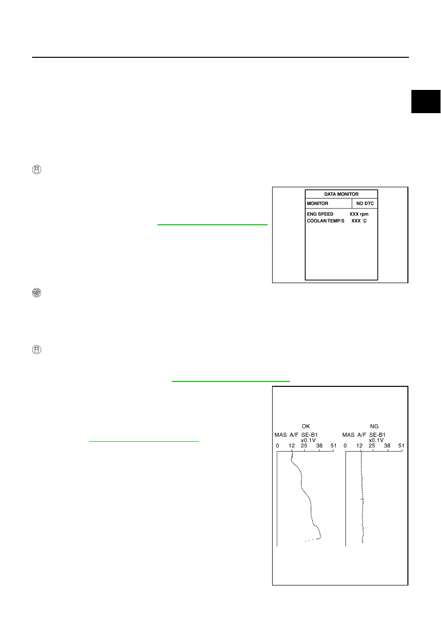
Select “DATA MONITOR” mode with CONSULT-II.
4.
Check the voltage of “MAS A/F SE-B1” with “DATA MONITOR”.
5.
Increases engine speed to about 4,000 rpm.
6.
Monitor the linear voltage rise in response to engine speed
increases.
If NG, go to
EC-910, "Diagnostic Procedure"
If OK, go to following step.
SEF174Y
SEF243Y
EC-908
[VK45DE]
DTC P0101 MAF SENSOR
7.
Maintain the following conditions for at least 10 consecutive sec-
onds.
8.
If 1st trip DTC is detected, go to
EC-910, "Diagnostic Procedure"
.
Overall Function Check
NBS005C9
PROCEDURE FOR MALFUNCTION B
Use this procedure to check the overall function of the mass air flow sensor circuit. During this check, a DTC
might not be confirmed.
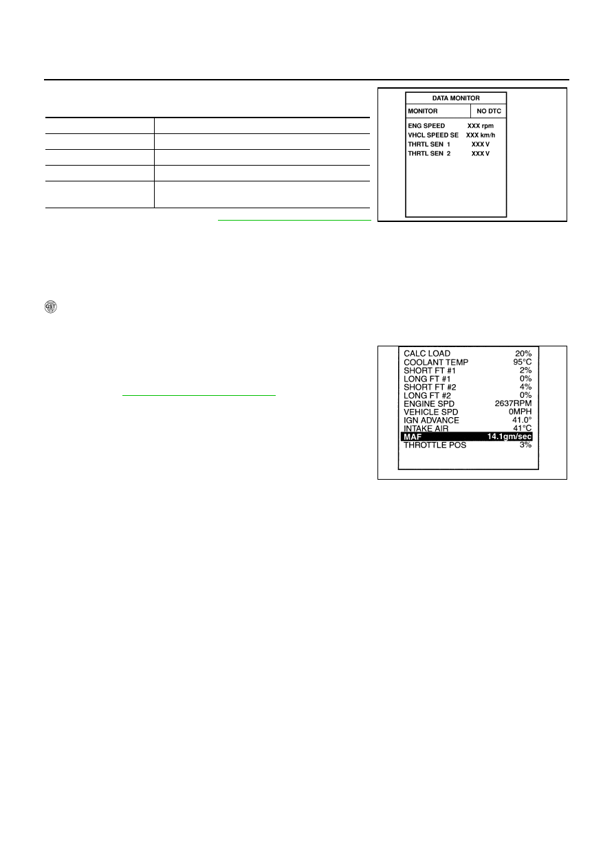
With GST
1.
Start engine and warm it up to normal operating temperature.
2.
Select Service $01 with GST.
3.
Check the mass air flow sensor signal with Service $01.
4.
Check for linear mass air flow sensor signal value rise in
response to increases to about 4,000 rpm in engine speed.
5.
If NG, go to
EC-910, "Diagnostic Procedure"
ENG SPEED
More than 2,000 rpm
THRTL SEN 1
More than 3V
THRTL SEN 2
More than 3V
Selector lever
Suitable position
Driving location
Driving vehicle uphill (Increased engine load) will help
maintain the driving conditions required for this test.
PBIB0199E
SEF534P
Нет комментариевНе стесняйтесь поделиться с нами вашим ценным мнением.
Текст