Infiniti M35/M45 Y50. Manual — part 1130
TROUBLE DIAGNOSIS FOR SYSTEM
TF-27
C
E
F
G
H
I
J
K
L
M
A
B
TF
2.
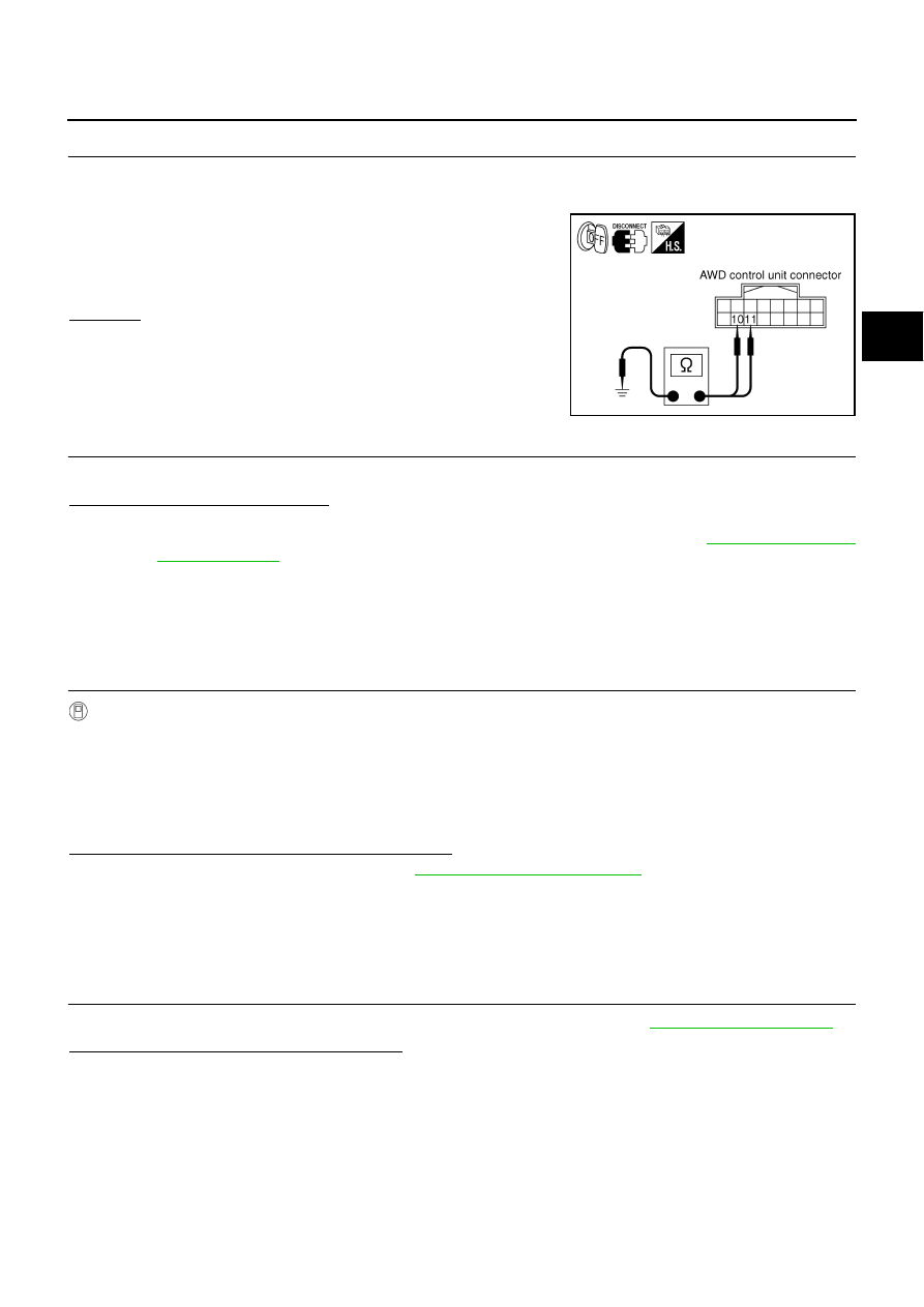
CHECK GROUND CIRCUIT
1.
Turn ignition switch “OFF”.
2.
Disconnect AWD control unit harness connector.
3.
Check continuity between AWD control unit harness connector
F109 terminals 10, 11 and ground.
Also check harness for short to ground and short to power.
OK or NG
OK
>> GO TO 3.
NG
>> Repair open circuit or short to ground or short to power
in harness or connectors.
3.
CHECK DTC
Start engine.
Does AWD warning lamp turn OFF?
YES
>> INSPECTION END
NO
>> Perform the self-diagnosis, repair or replace damaged parts. Refer to
.
AWD Control Unit
NDS000DO
DIAGNOSTIC PROCEDURE
●
Check the following if “CONTROLLER FAILURE [C1201]” is displayed in self-diagnosis results of CON-
SULT-II.
1.
PERFORM SELF-DIAGNOSIS
With CONSULT-II
1.
Turn ignition switch “ON”. (Do not start engine.)
2.
Select “SELF-DIAG RESULTS” mode for “ALL MODE AWD/4WD” with CONSULT-II.
3.
Touch “ERASE”.
4.
Turn ignition switch “OFF” and wait at least 10 seconds.
5.
Perform the self-diagnosis again.
Is the “CONTROLLER FAILURE [C1201]” displayed?
YES
>> Replace AWD control unit. Refer to
NO
>> INSPECTION END
ABS System
NDS000DP
DIAGNOSTIC PROCEDURE
●
Check the following if “ABS SYSTEM [C1203]” is displayed in self-diagnosis results of CONSULT-II.
1.
CHECK DTC WITH ABS ACTUATOR AND ELECTRIC UNIT (CONTROL UNIT)
Perform self-diagnosis with ABS actuator and electric unit (control unit). Refer to
.
Is any malfunction detected by self-diagnosis?
YES
>> Check the malfunctioning system.
NO
>> GO TO 2.
Continuity should exist.
SDIA1883E
TF-28
TROUBLE DIAGNOSIS FOR SYSTEM
2.
CHECK DTC AFTER DRIVING
1.
Turn ignition switch “OFF”.
2.
Start engine and drive vehicle at 30 km/h (19 MPH) for at least 1 minute.
3.
Make sure that ABS warning lamp turns OFF.
4.
Perform erase self-diagnosis results. Refer to
TF-22, "How to Erase Self-Diagnostic Results"
5.
Stop vehicle and turn ignition switch “OFF”.
6.
Turn ignition switch “ON”.
7.
Perform self-diagnosis.
Is the “ABS SYSTEM [C1203]” displayed?
YES
>> GO TO 3.
NO
>> INSPECTION END
3.
CHECK AWD CONTROL UNIT
Check AWD control unit input/output signal. Refer to
TF-20, "AWD Control Unit Input/Output Signal Reference
OK or NG
OK
>> GO TO 4.
NG
>> Check AWD control unit pin terminals for damage or loose connection with harness connector. If
any items are damaged, repair or replace damaged parts.
4.
CHECK DTC
Perform the self-diagnosis, after driving a vehicle for a while.
OK or NG
OK
>> INSPECTION END
NG
>> Perform self-diagnosis with ABS actuator and electric unit (control unit) again. Refer to
AWD Solenoid
NDS000DQ
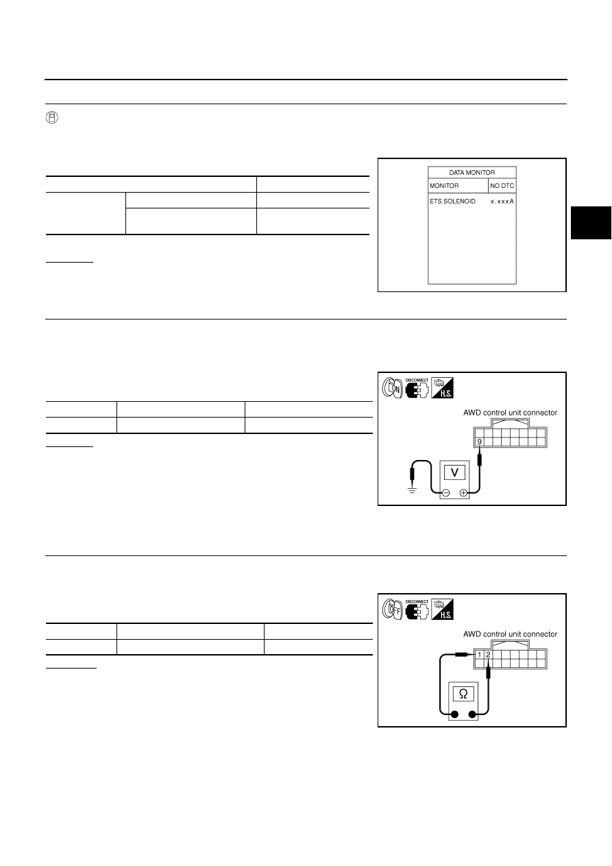
CONSULT-II REFERENCE VALUE IN DATA MONITOR MODE
Data are reference value.
*: The values are changed by throttle opening and engine speed.
DIAGNOSTIC PROCEDURE
●
Check the following if “4WD SOLENOID [C1204]” is displayed in self-diagnosis results of CONSULT-II.
Monitor item [Unit]
Condition
Display value
ETS SOLENOID [A]
Engine running
At idle speed
Approx. 0.000A
When depressing accelerator pedal
Approx. 0.000 - 0.500A*
TROUBLE DIAGNOSIS FOR SYSTEM
TF-29
C
E
F
G
H
I
J
K
L
M
A
B
TF
1.
CHECK AWD SOLENOID SIGNAL
With CONSULT-II
1.
Start engine.
2.
Select “DATA MONITOR” mode for “ALL MODE AWD/4WD” with CONSULT-II.
3.
Read out the value of “ETS SOLENOID”.
*: The values are changed by throttle opening and engine speed.
OK or NG
OK >> GO
TO
6.
NG
>> GO TO 2.
2.
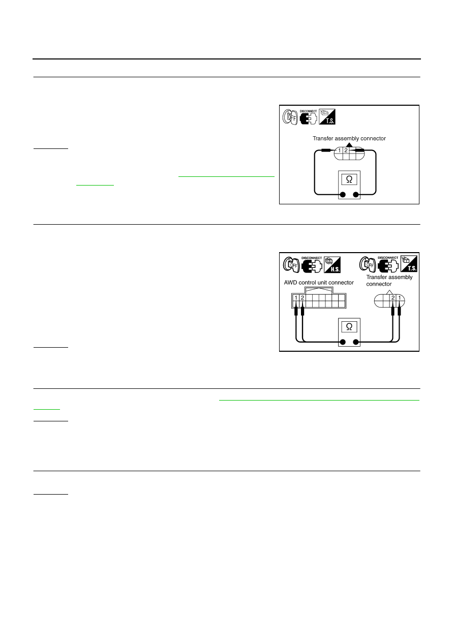
CHECK POWER SUPPLY
1.
Turn ignition switch “OFF”.
2.
Disconnect AWD control unit harness connector.
3.
Turn ignition switch “ON”. (Do not start engine.)
4.
Check voltage between AWD control unit harness connector ter-
minal 9 and ground.
OK or NG
OK
>> GO TO 3.
NG
>> Check the following. If any items are damaged, repair or
replace damaged parts.
●
10A fuse [No. 33, located in the fuse block (J/B)]
●
Harness for short or open between battery and AWD
control unit harness connector terminal 9
3.
CHECK AWD SOLENOID CIRCUIT
1.
Turn ignition switch “OFF”.
2.
Disconnect AWD control unit harness connector.
3.
Check resistance between AWD control unit harness connector
terminals 1 and 2.
OK or NG
OK
>> GO TO 6.
NG
>> GO TO 4.
Condition
Display value
Engine running
At idle speed
Approx. 0.000A
When depressing accelerator
pedal
Approx. 0.000 - 0.500A*
SDIA1885E
Connector
Terminal
Voltage (Approx.)
F109
9 - Ground
Battery voltage
SDIA1884E
Connector
Terminal
Resistance (Approx.)
F109
1 - 2 (Ground)
2.45
Ω
SDIA1928E
TF-30
TROUBLE DIAGNOSIS FOR SYSTEM
4.
CHECK AWD SOLENOID
1.
Turn ignition switch “OFF”.
2.
Disconnect transfer assembly harness connector.
3.
Check resistance between transfer assembly harness connector
F43 terminals 1 and 2.
OK or NG
OK
>> GO TO 5.
NG
>> AWD solenoid is malfunctioning. Replace electric con-
trolled coupling. Refer to
.
5.
CHECK HARNESS BETWEEN AWD CONTROL UNIT AND AWD SOLENOID
1.
Turn ignition switch “OFF”.
2.
Disconnect AWD control unit harness connector and transfer assembly harness connector.
3.
Check continuity between the following terminals.
–
AWD control unit harness connector F109 terminal 1 and trans-
fer assembly harness connector F43 terminal 1.
–
AWD control unit harness connector F109 terminal 2 and trans-
fer assembly harness connector F43 terminal 2.
Also check harness for short to ground and short to power.
OK or NG
OK
>> GO TO 6.
NG
>> Repair or replace damaged parts.
6.
CHECK AWD CONTROL UNIT
Check AWD control unit input/output signal. Refer to
TF-20, "AWD Control Unit Input/Output Signal Reference
OK or NG
OK
>> GO TO 7.
NG
>> Check AWD control unit pin terminals for damage or loose connection with harness connector. If
any items are damaged, repair or replace damaged parts.
7.
CHECK DTC
Perform the self-diagnosis, after driving a vehicle for a while.
OK or NG
OK
>> INSPECTION END
NG
>> Replace AWD control unit.
COMPONENT INSPECTION
1.
Turn ignition switch “OFF”.
2.
Disconnect transfer assembly harness connector.
1 - 2
: Approx. 2.45
Ω
SDIA2162E
1 - 1
: Continuity should exist.
2 - 2
: Continuity should exist.
SDIA2163E
Нет комментариевНе стесняйтесь поделиться с нами вашим ценным мнением.
Текст