Infiniti M35/M45 Y50. Manual — part 1131
TROUBLE DIAGNOSIS FOR SYSTEM
TF-31
C
E
F
G
H
I
J
K
L
M
A
B
TF
3.
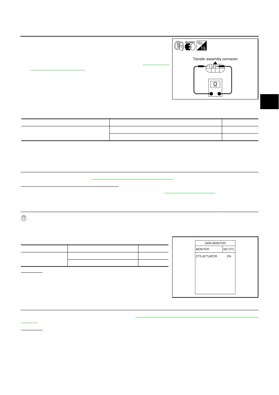
Check resistance between transfer assembly harness connector
F43 terminals 1 and 2.
4.
If NG, replace electric controlled coupling. Refer to
AWD Actuator Relay
NDS000DR
CONSULT-II REFERENCE VALUE IN DATA MONITOR MODE
Data are reference value.
DIAGNOSTIC PROCEDURE
●
Check the following if “4WD ACTUATOR RLY [C1205]” is displayed in self-diagnosis results of CONSULT-
II.
1.
CHECK AWD SOLENOID SYSTEM
Perform self-diagnosis. Refer to
TF-22, "SELF-DIAG RESULT MODE"
Is the “4WD SOLENOID [C1204]” displayed?
YES
>> Perform trouble diagnosis for AWD solenoid. Refer to
NO
>> GO TO 2.
2.
CHECK AWD ACTUATOR RELAY SIGNAL
With CONSULT-II
1.
Turn ignition switch “ON”. (Do not start engine.)
2.
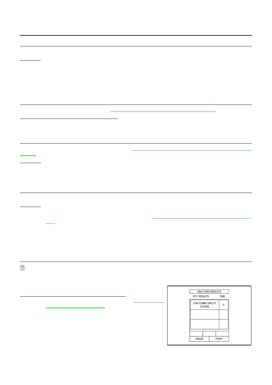
Select “DATA MONITOR” mode for “ALL MODE AWD/4WD” with CONSULT-II.
3.
Start engine and read out ON/OFF signal of “ETS ACTUATOR”.
OK or NG
OK >> GO
TO
4.
NG
>> GO TO 3.
3.
CHECK AWD CONTROL UNIT
Check AWD control unit input/output signal. Refer to
TF-20, "AWD Control Unit Input/Output Signal Reference
OK or NG
OK
>> GO TO 4.
NG
>> Check AWD control unit pin terminals for damage or loose connection with harness connector. If
any items are damaged, repair or replace damaged parts.
1 - 2
: Approx. 2.45
Ω
SDIA2162E
Monitor item
Condition
Display value
ETS ACTUATOR [ON/OFF]
Engine stopped (Ignition switch: ON)
OFF
Engine running
ON
Monitor item
Condition
Display value
ETS ACTUATOR
Engine stopped (Ignition switch: ON)
OFF
Engine running
ON
SDIA1897E
TF-32
TROUBLE DIAGNOSIS FOR SYSTEM
4.
CHECK DTC
Perform the self-diagnosis, after driving a vehicle for a while.
OK or NG
OK
>> INSPECTION END
NG
>> Replace AWD control unit.
Engine Control Signal
NDS000DS
DIAGNOSTIC PROCEDURE
●
Check the following if “ECM SIGNAL 1 [C1210]” is displayed in self-diagnosis results of CONSULT-II.
1.
CHECK DTC WITH ECM
Perform self-diagnosis with ECM. Refer to
EC-55, "Emission-Related Diagnostic Information"
.
Is any malfunction detected by self-diagnosis?
YES
>> Check the malfunctioning system.
NO
>> GO TO 2.
2.
CHECK AWD CONTROL UNIT
Check AWD control unit input/output signal. Refer to
TF-20, "AWD Control Unit Input/Output Signal Reference
OK or NG
OK
>> GO TO 3.
NG
>> Check AWD control unit pin terminals for damage or loose connection with harness connector. If
any items are damaged, repair or replace damaged parts.
3.
CHECK DTC
Perform the self-diagnosis, after driving a vehicle for a while.
OK or NG
OK
>> INSPECTION END
NG
>> Perform self-diagnosis with ECM again. Refer to
EC-55, "Emission-Related Diagnostic Informa-
CAN Communication Line
NDS000DT
DIAGNOSTIC PROCEDURE
●
Check the following if “CAN COMM CIRCUIT [U1000]” is detected in self-diagnosis results of CONSULT-
II.
1.
CHECK CAN COMMUNICATION CIRCUIT
With CONSULT-II
1.
Turn ignition switch “ON” and start engine.
2.
Select “SELF-DIAG RESULTS” mode for “ALL MODE AWD/4WD” with in CONSULT-II.
3.
Perform the self-diagnosis.
Is the “CAN COMM CIRCUIT [U1000]” displayed?
YES
>> Print out CONSULT-II screen and go to
NO
>> INSPECTION END
SDIA1850E
TROUBLE DIAGNOSIS FOR SYMPTOMS
TF-33
C
E
F
G
H
I
J
K
L
M
A
B
TF
TROUBLE DIAGNOSIS FOR SYMPTOMS
PFP:00007
AWD Warning Lamp Does Not Turn ON When The Ignition Switch Is Turned to
ON
NDS000DU
DIAGNOSTIC PROCEDURE
1.
CHECK SYSTEM FOR CAN COMMUNICATION LINE
Perform self-diagnosis. Refer to
TF-22, "SELF-DIAG RESULT MODE"
Is the “CAN COMM CIRCUIT [U1000]” displayed?
YES
>> Perform trouble diagnosis for CAN communication line. Refer to
NO
>> GO TO 2.
2.
CHECK AWD CONTROL UNIT
Check AWD control unit input/output signal. Refer to
TF-20, "AWD Control Unit Input/Output Signal Reference
OK or NG
OK
>> GO TO 3.
NG
>> Check AWD control unit pin terminals for damage or loose connection with harness connector. If
any items are damaged, repair or replace damaged parts.
3.
CHECK OUTPUT SIGNAL WITH UNIFIED METER AND A/C AMP.
With CONSULT-II
1.
Turn ignition switch “ON”. (Do not start engine.)
2.
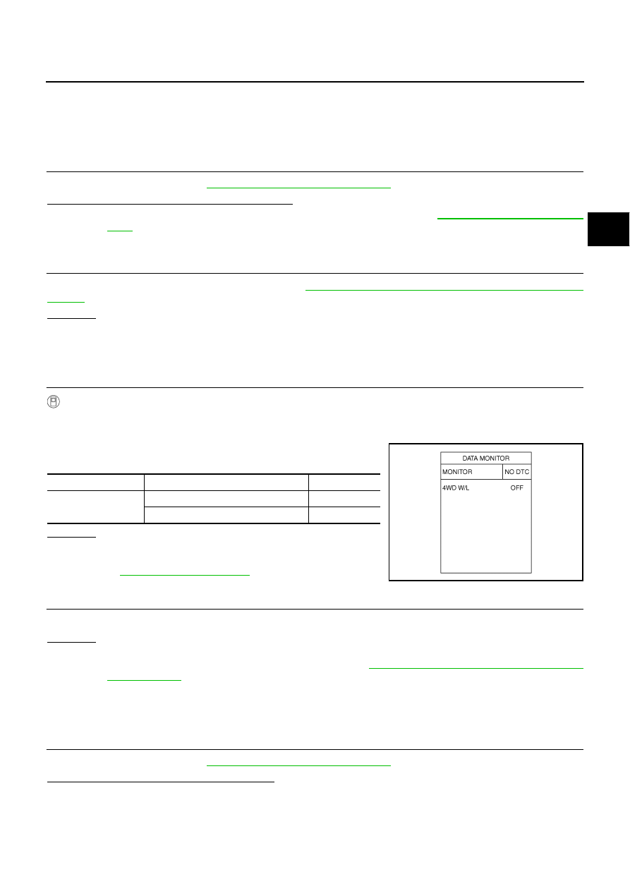
Select “DATA MONITOR” mode for “METER A/C AMP” with CONSULT-II.
3.
Start the engine, and then make sure that “4WD W/L” display
turns from "ON" to "OFF" after several seconds.
OK or NG
OK >> GO
TO
4.
NG
>> Perform trouble diagnosis for combination meter. Refer
to
.
4.
SYMPTOM CHECK
Check again.
OK or NG
OK
>> INSPECTION END
NG
>> Replace unified meter control unit assembly. Refer to
DI-27, "Disassembly and Assembly of Com-
AWD Warning Lamp Does Not Turn OFF Several Seconds after Engine Started
NDS000DV
DIAGNOSTIC PROCEDURE
1.
CHECK SELF-DIAGNOSTIC RESULTS
Perform self-diagnosis. Refer to
TF-22, "SELF-DIAG RESULT MODE"
Is any malfunction detected by self-diagnosis?
YES
>> Check the malfunctioning system.
NO
>> GO TO 2.
Monitor item
Condition
Display value
4WD W/L
Ignition switch ON
ON
Start engine (after several seconds)
OFF
SDIA2065E
TF-34
TROUBLE DIAGNOSIS FOR SYMPTOMS
2.
CHECK AWD CONTROL UNIT POWER SUPPLY CIRCUIT
1.
Turn ignition switch “OFF”.
2.
Disconnect AWD control unit harness connector.
3.
Turn ignition switch “ON”. (Do not start engine.)
4.
Check voltage between AWD control unit harness connector ter-
minals and ground.
5.
Turn ignition switch “OFF”.
6.
Check voltage between AWD control unit harness connector ter-
minals and ground.
OK or NG
OK
>> GO TO 3.
NG
>> Check the following. If any items are damaged, repair or
replace damaged parts.
●
10A fuse [No.33, located in the fuse block (J/B)]
●
10A fuse [No.82, located in the IPDM E/R]
●
Harness for short or open between battery and AWD control unit harness connector terminal 9
●
Harness for short or open between ignition switch and AWD control unit harness connector ter-
minal 7
●
PG-3, "POWER SUPPLY ROUTING CIRCUIT"
3.
CHECK AWD CONTROL UNIT GROUND CIRCUIT
1.
Turn ignition switch “OFF”.
2.
Disconnect AWD control unit harness connector.
3.
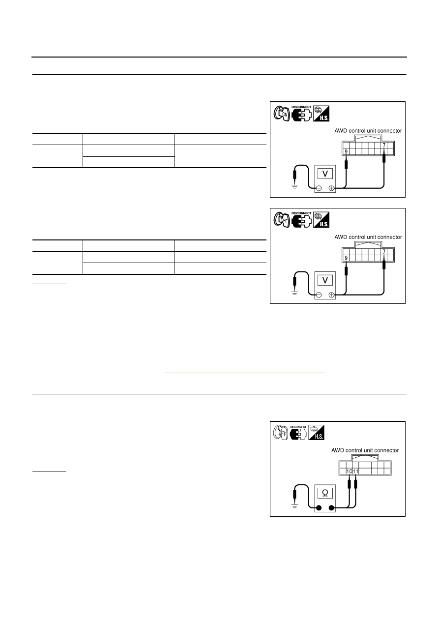
Check continuity between AWD control unit harness connector
F109 terminals 10, 11 and ground.
Also check harness for short to ground and short to power.
OK or NG
OK
>> GO TO 4.
NG
>> Repair open circuit or short to ground or short to power
in harness or connectors.
Connector
Terminal Voltage
(Approx.)
F109
7 - Ground
Battery voltage
9 - Ground
SDIA2319E
Connector
Terminal Voltage
(Approx.)
F109
7 - Ground
0V
9 - Ground
Battery voltage
SDIA2320E
Continuity should exist.
SDIA1883E
Нет комментариевНе стесняйтесь поделиться с нами вашим ценным мнением.
Текст