Infiniti M35/M45 Y50. Manual — part 1046
STARTING SYSTEM
SC-19
C
D
E
F
G
H
I
J
L
M
A
B
SC
VK45DE ENGINE MODELS
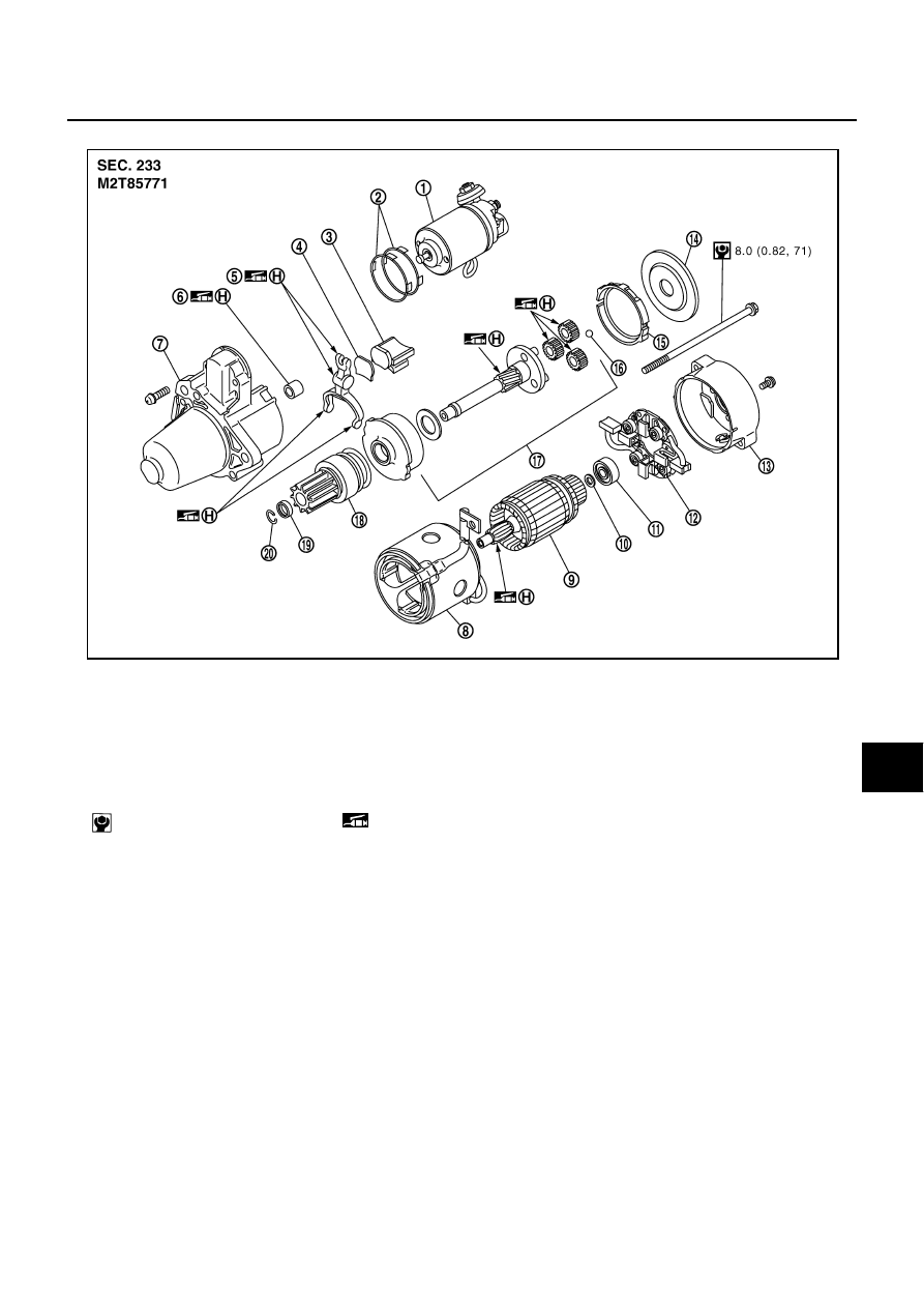
Inspection After Disassembly
NKS005BW
PINION/CLUTCH CHECK
1.
Inspect pinion teeth.
●
Replace pinion if teeth are worn or damaged. (Also check condition of ring gear teeth.)
2.
Inspect reduction gear teeth.
●
Replace reduction gear if teeth are worn or damaged. (Also check condition of armature shaft gear
teeth.)
3.
Check if pinion locks in one direction and rotates smoothly in the opposite direction.
●
If it locks or rotates in both directions, or unusual resistance is evident, replace.
1.
Magnetic switch assembly
2.
Adjusting plate
3.
Packing
4.
Plate
5.
Shift lever
6.
Sleeve bearing
7.
Front bracket assembly
8.
Yoke assembly
9.
Armature assembly
10.
Washer
11.
Rear bearing
12. Brush holder assembly
13.
Rear bracket assembly
14.
Cover
15. Packing
16.
Ball
17.
Shaft gear assembly
18. Clutch gear assembly
19.
Pinion stopper
20.
Stopper clip
: N·m (kg-m, in-lb)
(H): High-temperature grease point
PKIB8653E
SC-20
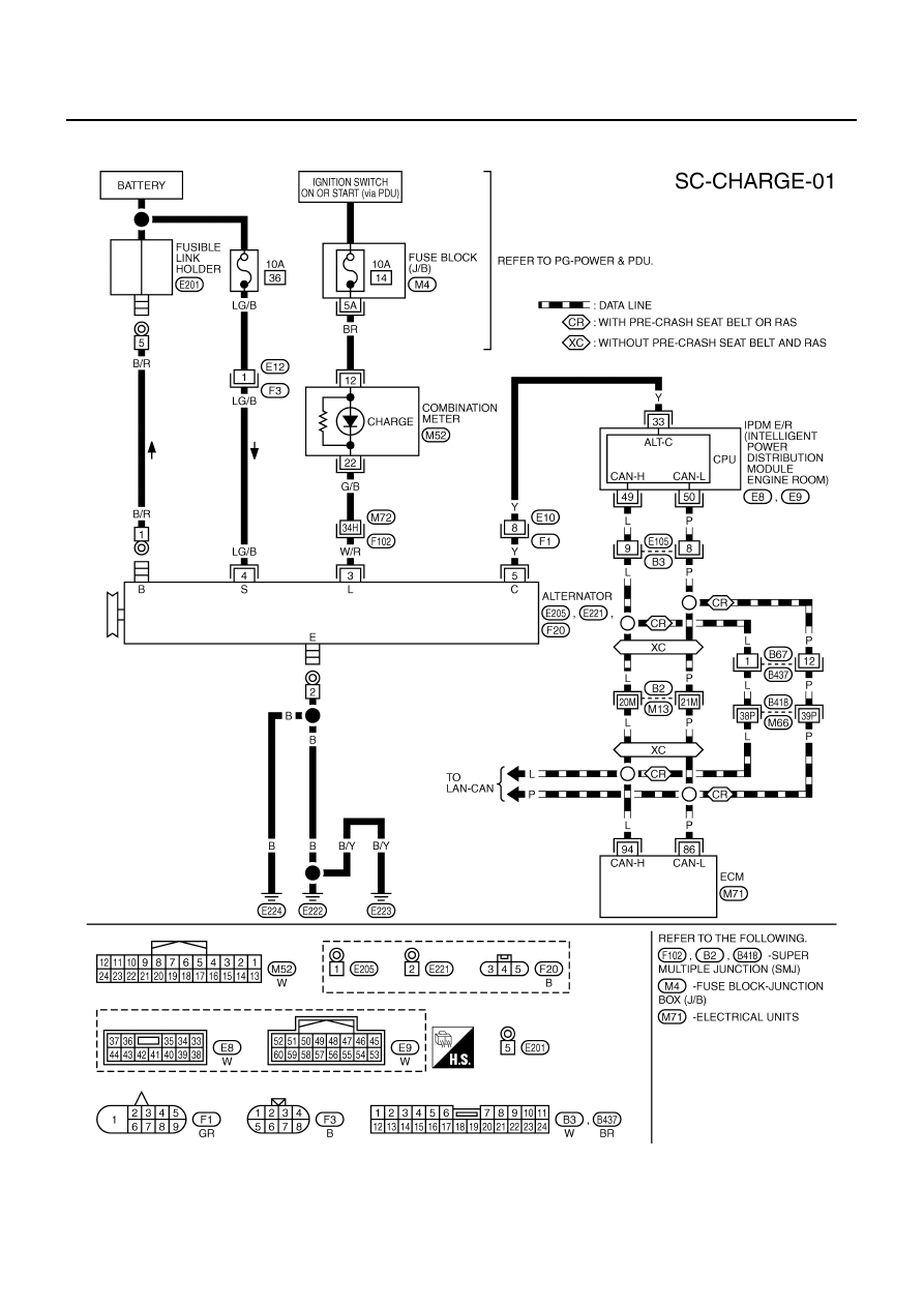
CHARGING SYSTEM
CHARGING SYSTEM
PFP:23100
System Description
NKS005BX
DESCRIPTION
The alternator provides DC voltage to operate the vehicle's electrical system and to keep the battery charged.
The voltage output is controlled by the IC regulator.
Power is supplied at all times
●
through 10A fuse [No. 36, located in the fuse, fusible link and relay block (J/B)]
●
to alternator terminal 4 (“S” terminal).
“B” terminal supplies power to charge the battery and operate the vehicle's electrical system. Output voltage is
controlled by the IC regulator at terminal 4 (“S” terminal) detecting the input voltage.
The alternator is grounded to the engine block.
With the ignition switch in the ON or START position, power is supplied
●
through 10A fuse [No. 14, located in the fuse block (J/B)]
●
to combination meter terminal 12 for the charge warning lamp.
Ground is supplied at signal
●
to combination meter terminal 22
●
through alternator terminal 3 (“L” terminal).
Then power and ground are supplied, the charge warning lamp will illuminate.
When the alternator is providing sufficient voltage with the engine running, the ground is opened and the
charge warning lamp will go off.
If the charge warning lamp illuminates with the engine running, a malfunction is indicated.
Ground is supplied
●
to alternator terminal 2 (“E” terminal)
●
through grounds E222, E223 and E224. (VQ35DE)
●
through ground E212. (VK45DE)
MALFUNCTION INDICATOR
The IC regulator warning function activates to illuminate the charge warning lamp, if any of the following symp-
toms occur while alternator is operating:
●
Excessive voltage is produced.
●
No voltage is produced.
CHARGING SYSTEM
SC-21
C
D
E
F
G
H
I
J
L
M
A
B
SC
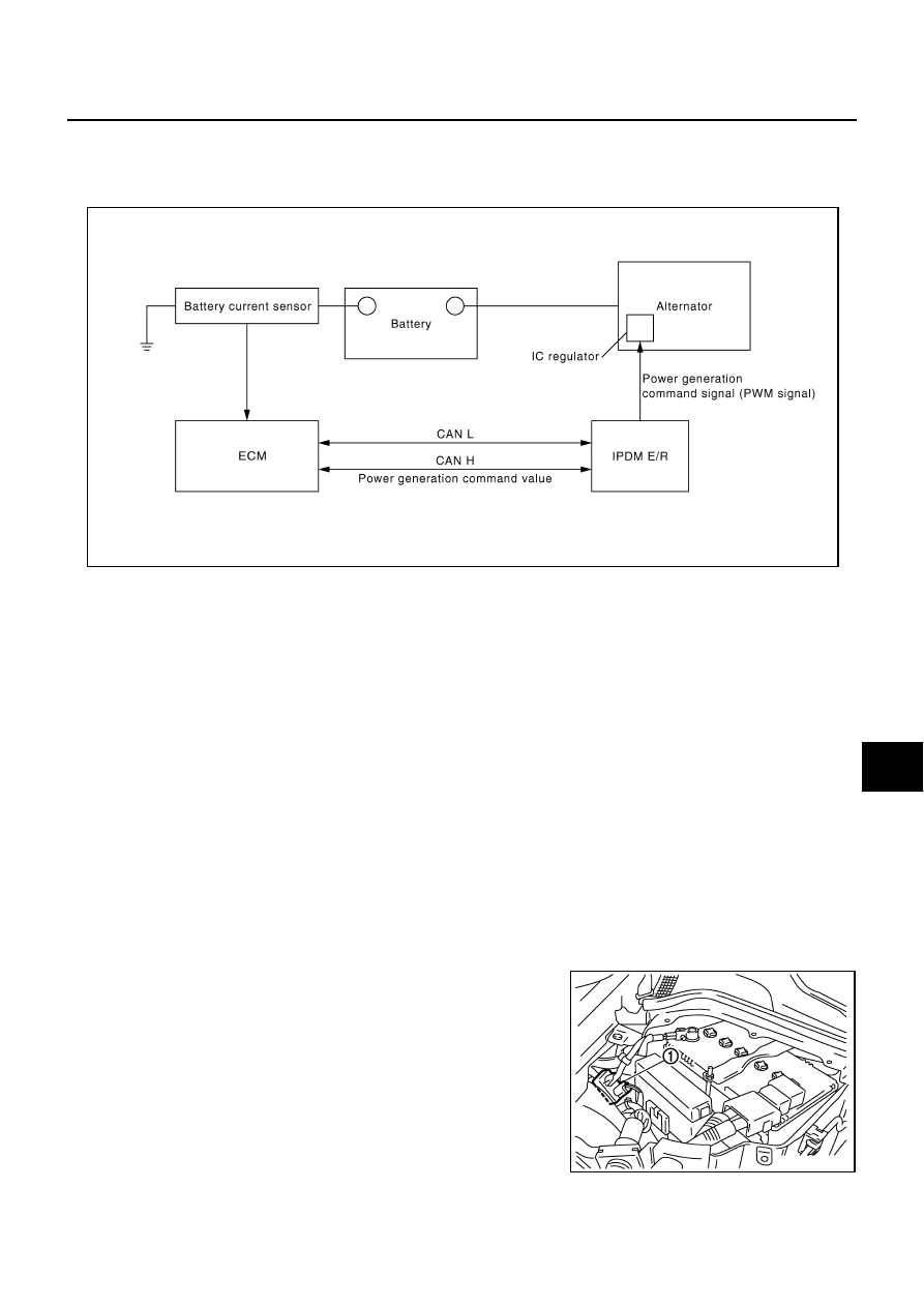
POWER GENERATION VOLTAGE VARIABLE CONTROL SYSTEM
Power generation voltage variable control system that controls the power generation voltage of the alternator
has been adopted. By performing the power generation voltage variable control, the engine load due to the
power generation of the alternator is reduced and fuel consumption is decreased.
Operation Description
●
The battery current sensor detects the charging/discharging current of the battery. ECM judges the battery
condition based on this signal.
●
ECM judges whether to perform the power generation voltage variable control according to the battery
condition.
●
When performing the power generation voltage variable control, ECM calculates the target power genera-
tion voltage according to the battery condition and sends the calculated value as the power generation
command value to IPDM E/R.
●
IPDM E/R converts the received power generation command value into the power generation command
signal (PWM signal) and sends it to the IC regulator.
●
The IC regulator controls the power generation voltage by the target power generation voltage based on
the received power generation command signal.
●
When there is no power generation command signal, the alternator performs the normal power generation
according to the characteristic of the IC regulator.
NOTE:
When any malfunction is detected in the power generation voltage variable control system, the power genera-
tion is performed according to the characteristic of the IC regulator of the alternator.
Main Component Part
BATTERY CURRENT SENSOR
●
Battery current sensor (1) is installed to the battery cable at the
negative terminal, and it detects the charging/discharging cur-
rent of the battery and sends the voltage signal to ECM accord-
ing to the current value.
SKIB5009E
PKIB8806E
SC-22
CHARGING SYSTEM
Wiring Diagram — CHARGE —
NKS005BY
VQ35DE ENGINE MODELS (2WD)
TKWT5247E
Нет комментариевНе стесняйтесь поделиться с нами вашим ценным мнением.
Текст