Infiniti M35/M45 Y50. Manual — part 684

DTC P1140, P1145 IVT CONTROL POSITION SENSOR
EC-1209
[VK45DE]
C
D
E
F
G
H
I
J
K
L
M
A
EC
5.
DETECT MALFUNCTIONING PART
Check the following.
●
Harness connectors F102, M72
●
Harness for open or short between intake valve timing control position sensor and ground
>> Repair open circuit or short to power in harness or connectors.
6.
CHECK INTAKE VALVE TIMING CONTROL POSITION SENSOR INPUT SIGNAL CIRCUIT FOR OPEN
AND SHORT
1.
Disconnect ECM harness connector.
2.
Check harness continuity between the following;
ECM terminal 72 and intake valve timing control position sensor (bank 1) terminal 2 or
ECM terminal 53 and intake valve timing control position sensor (bank 2) terminal 2.
Refer to Wiring Diagram.
3.
Also check harness for short to ground and short to power.
OK or NG
OK
>> GO TO 7.
NG
>> Repair open circuit or short to ground or short to power in harness or connectors.
7.
CHECK INTAKE VALVE TIMING CONTROL POSITION SENSOR
Refer to
EC-1210, "Component Inspection"
.
OK or NG
OK
>> GO TO 8.
NG
>> Replace intake valve timing control position sensor.
8.
CHECK CRANKSHAFT POSITION SENSOR (POS)
Refer to
EC-1081, "Component Inspection"
.
OK or NG
OK
>> GO TO 9.
NG
>> Replace crankshaft position sensor (POS).
9.
CHECK CAMSHAFT POSITION SENSOR (PHASE)
Refer to
EC-1088, "Component Inspection"
.
OK or NG
OK
>> GO TO 10.
NG
>> Replace camshaft position sensor (PHASE).
10.
CHECK CAMSHAFT SPROCKET
Check accumulation of debris to the signal pick-up portion of the camshaft sprocket. Refer to
OK or NG
OK
>> GO TO 11.
NG
>> Remove debris and clean the signal pick-up cutout of camshaft sprocket.
11.
CHECK INTERMITTENT INCIDENT
Refer to
EC-857, "TROUBLE DIAGNOSIS FOR INTERMITTENT INCIDENT"
>> INSPECTION END
Continuity should exist.
EC-1210
[VK45DE]
DTC P1140, P1145 IVT CONTROL POSITION SENSOR
Component Inspection
NBS005KF
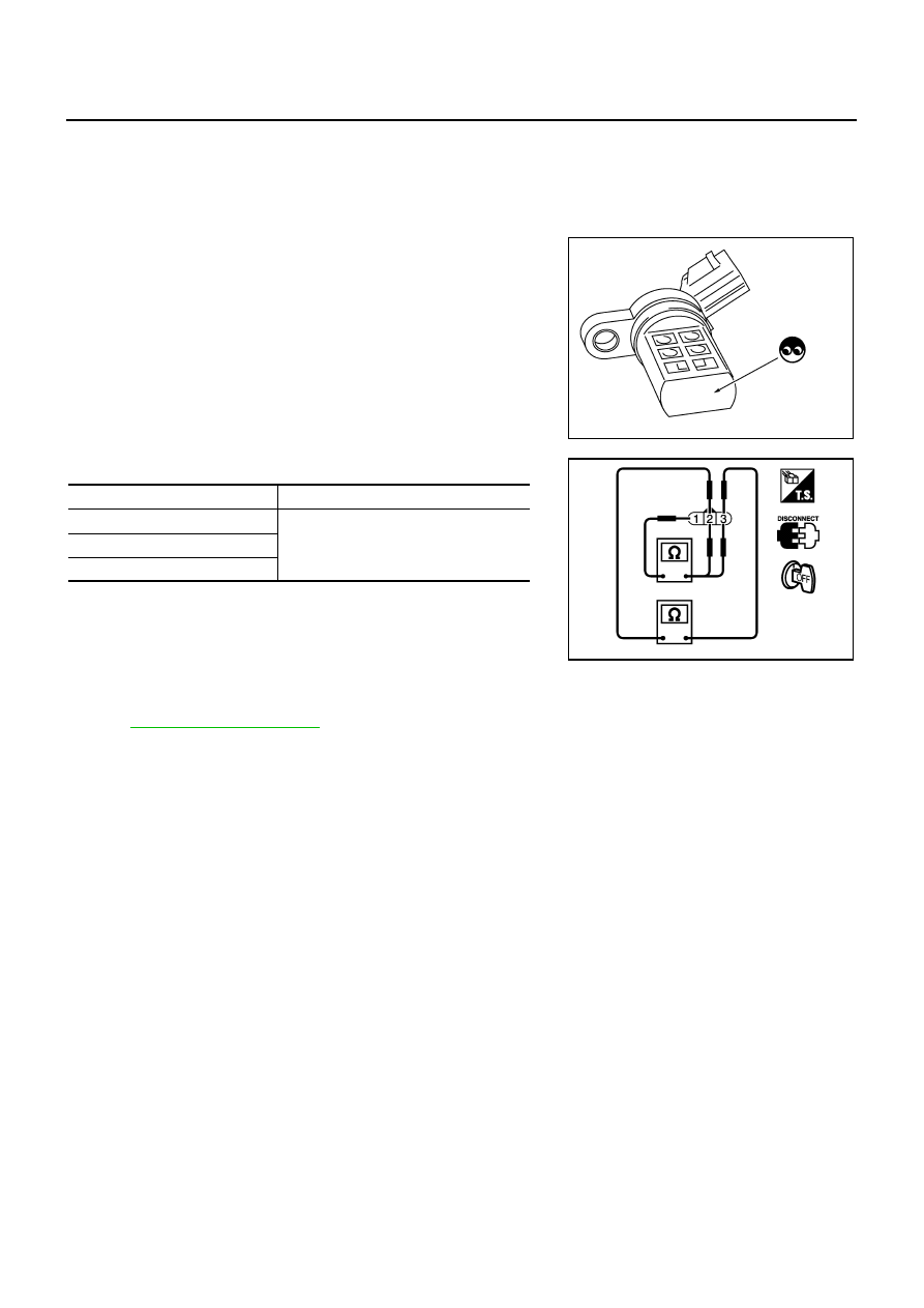
INTAKE VALVE TIMING CONTROL POSITION SENSOR
1.
Disconnect intake valve timing control position sensor harness connector.
2.
Loosen the fixing bolt of the sensor.
3.
Remove the sensor.
4.
Visually check the sensor for chipping.
5.
Check resistance as shown below.
6.
If NG, replace intake valve timing control position sensor.
Removal and Installation
NBS005KG
INTAKE VALVE TIMING CONTROL POSITION SENSOR
Refer to
SEF362Z
Terminal No. (Polarity)
Resistance
Ω
[at 25
°
C (77
°
F)]
3 (+) - 1 (-)
Except 0 or
∞
2 (+) - 1 (-)
3 (+) - 2 (-)
PBIB0194E

DTC P1148, P1168 CLOSED LOOP CONTROL
EC-1211
[VK45DE]
C
D
E
F
G
H
I
J
K
L
M
A
EC
DTC P1148, P1168 CLOSED LOOP CONTROL
PFP:22690
On Board Diagnosis Logic
NBS005KH
These self-diagnoses have the one trip detection logic.
NOTE:
DTC P1148 or P1168 is displayed with another DTC for A/F sensor 1.
Perform the trouble diagnosis for the corresponding DTC.
DTC No.
Trouble diagnosis name
DTC detecting condition
Possible cause
P1148
1148
(Bank 1)
Closed loop control
function
The closed loop control function for bank 1
does not operate even when vehicle is driving
in the specified condition.
●
Harness or connectors
(The A/F sensor 1 circuit is open or
shorted.)
●
A/F sensor 1
●
A/F sensor 1 heater
P1168
1168
(Bank 2)
The closed loop control function for bank 2
does not operate even when vehicle is driving
in the specified condition.
EC-1212
[VK45DE]
DTC P1211 TCS CONTROL UNIT
DTC P1211 TCS CONTROL UNIT
PFP:47850
Description
NBS005KI
The malfunction information related to TCS is transferred through the CAN communication line from “ABS
actuator and electric unit (control unit)” to ECM.
Be sure to erase the malfunction information such as DTC not only for “ABS actuator and electric unit
(control unit)” but also for ECM after TCS related repair.
On Board Diagnosis Logic
NBS005KJ
Freeze frame data is not stored in the ECM for this self-diagnosis. The MIL will not light up for this self-
diagnosis.
DTC Confirmation Procedure
NBS005KK
TESTING CONDITION:
Before performing the following procedure, confirm that battery voltage is more than 10.5V at idle.
WITH CONSULT-II
1.
Turn ignition switch ON.
2.
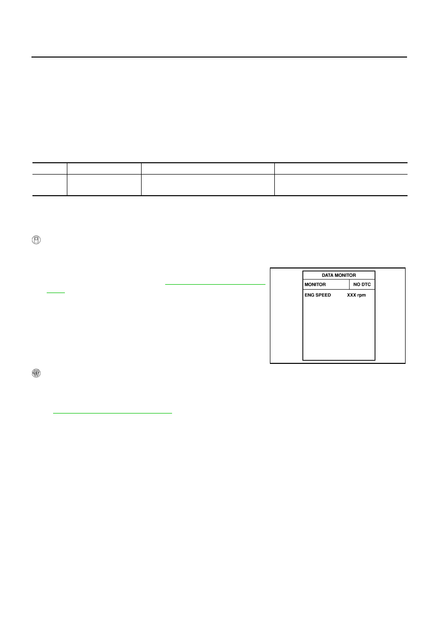
Select “DATA MONITOR” mode with CONSULT-II.
3.
Start engine and let it idle for at least 60 seconds.
4.
If 1st trip DTC is detected, go to
.
WITH GST
Follow the procedure “WITH CONSULT-II” above.
Diagnostic Procedure
NBS005KL
DTC No.
Trouble diagnosis name
DTC detecting condition
Possible cause
P1211
1211
TCS control unit
ECM receives a malfunction information from
“ABS actuator electric unit (control unit)”
●
ABS actuator and electric unit (control unit)
●
TCS related parts
SEF058Y
Нет комментариевНе стесняйтесь поделиться с нами вашим ценным мнением.
Текст