Infiniti M35/M45 Y50. Manual — part 272
INTELLIGENT KEY SYSTEM/ENGINE START FUNCTION
BL-157
C
D
E
F
G
H
J
K
L
M
A
B
BL
4.
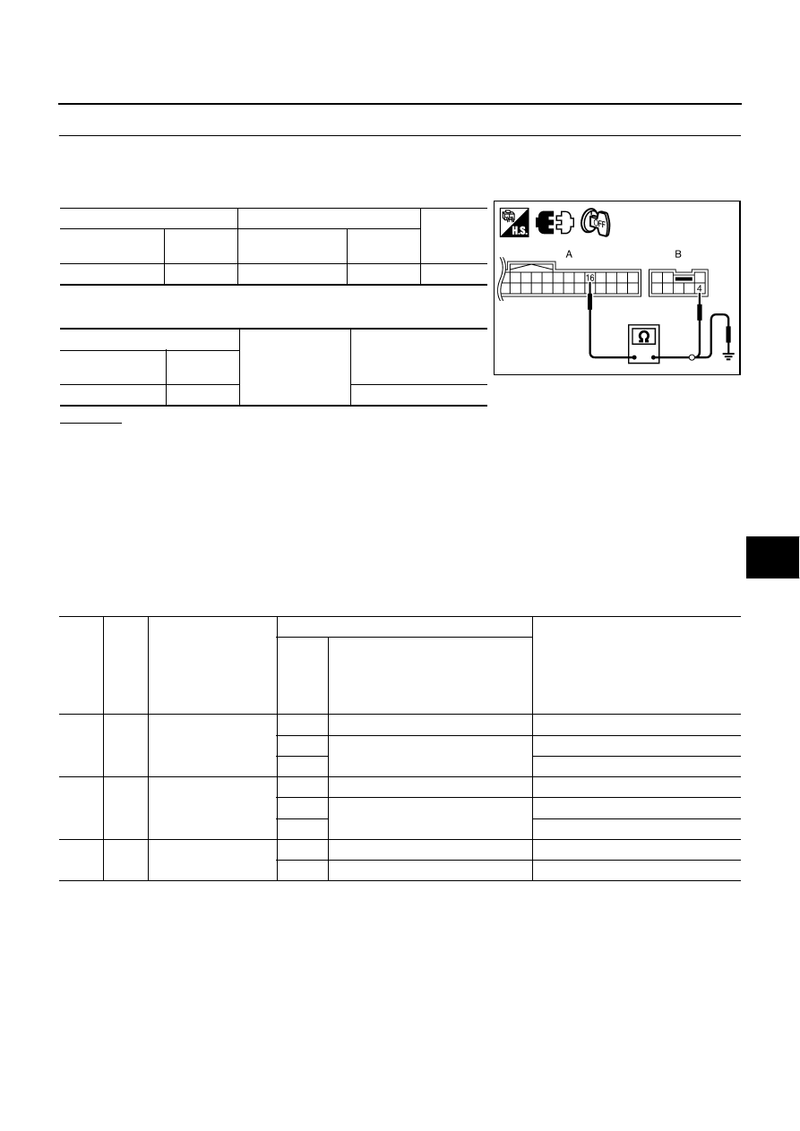
CHECK HARNESS CONTINUITY 2
1.
Turn ignition switch OFF.
2.
Disconnect Intelligent Key unit and steering lock unit connector.
3.
Check continuity between Intelligent Key unit connector and steering lock unit connector.
4.
Check continuity between Intelligent Key unit connector and
ground.
OK or NG
OK
>> Check the condition of harness and connector. If it is OK, check the self-diagnosis results using
CONSULT-II again.
NG
>> Repair or replace harness.
DTC B2551 STEERING LOCK UNIT
NIS001YO
DIAGNOSIS DESCRIPTION
Though the communication between the Intelligent Key unit and the steering lock unit is normal, when the
steering lock/unlock is not normal, B2551 steering lock unit malfunction judges that it is the malfunction and
displays the DTC (Diagnostic Trouble Code)
TERMINALS AND REFERENCE VALUE
Intelligent Key Unit
A
B
Continuity
Intelligent Key
unit connector
Terminal
Steering lock unit
connector
Terminal
M32
16
M35
4
Yes
A
Ground
Continuity
Intelligent Key unit
connector
Terminal
M32
16
No
PIIB6226E
Termi-
nal
No.
Wire
color
Item
Condition
Voltage (V)
(Approx.)
Push-
button
ignition
switch
position
Operation or conditions
69
O
Steering lock unit con-
dition signal-1
LOCK
Steering lock: Lock
0
ACC
Steering lock: Unlock
Battery voltage
ON
Battery voltage
70
L/Y
Steering lock unit con-
dition signal-2
LOCK
Steering lock: Lock
Battery voltage
ACC
Steering lock: Unlock
0
ON
0
71
LG
PDU signal
LOCK
Steering lock: Lock
Battery voltage
ACC
Steering lock: Unlocked moment
0
BL-158
INTELLIGENT KEY SYSTEM/ENGINE START FUNCTION
PDU (Power Distribution Unit)
SELF-DIAGNOSTIC LOGIC
DIAGNOSTIC PROCEDURE
1.
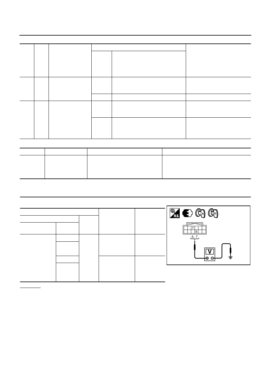
CHECK STEERING LOCK SIGNAL
Check voltage between power distribution unit connector and ground.
OK or NG
OK
>> GO TO 2.
NG
>> GO TO 4.
Ter-
minal
No.
Wire
color
Item
Condition
Voltage (V)
(Approx.)
Push-
button
ignition
switch
position
Operation or conditions
3
GR
Steering lock unit
power source
LOCK
Push-button ignition switch is pressed
under the condition that Intelligent Key is
in the vehicle or Intelligent Key is inserted
0
→
Battery voltage
→
0
—
Any condition other than above
0
7
LG
Steering lock control
signal-2
—
Push-button ignition switch is pressed
under the condition that Intelligent Key is
in the vehicle or Intelligent Key is inserted
Battery voltage
LOCK
Power supply position is in LOCK posi-
tion
(Steering lock activated)
Battery voltage
→
0
→
Battery voltage
(Battery voltage is detected when
activating the steering lock)
DTC
Self-diagnosis name
DTC detecting condition
Possible causes
B2551
STEERING LOCK
UNIT
Though the communication between the
Intelligent Key and the steering lock unit
is normal, the steering lock unit condition
signal is NG
●
Harness and connector
(Open or shorted in the circuit between the
units)
●
Steering lock unit
Terminals
Condition
Voltage (V)
(Approx.)
(+)
(–)
Power distribu-
tion unit connector
Terminal
M30
6
Ground
When turn ignition
switch to START
with Intelligent Key
in the car
Battery voltage
7
6
When turn ignition
switch to OFF
(steering lock
operates)
Battery voltage
↓
0
↓
Battery voltage
7
PIIB6227E
INTELLIGENT KEY SYSTEM/ENGINE START FUNCTION
BL-159
C
D
E
F
G
H
J
K
L
M
A
B
BL
2.
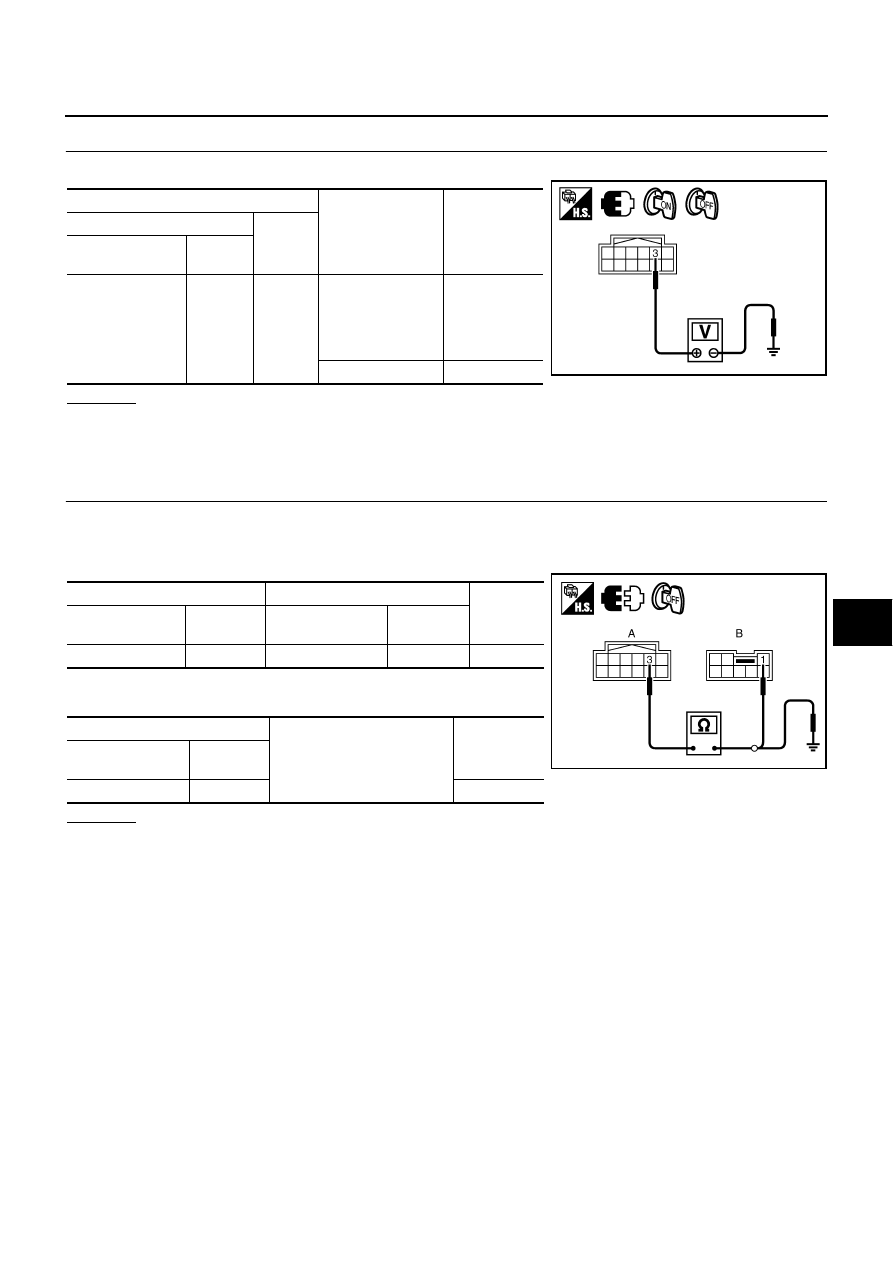
CHECK POWER DISTRIBUTION UNIT POWER SUPPLY
Check voltage between power distribution unit connector and ground.
OK or NG
OK
>> GO TO 3.
NG
>> Check if "B2558 PDU" is displayed on self-diagnosis results. If it is displayed, first perform the
diagnosis.
3.
CHECK POWER SUPPLY CIRCUIT
1.
Turn ignition switch OFF.
2.
Disconnect power distribution unit and steering lock unit connector.
3.
Check continuity between power distribution unit connector and steering lock unit connector.
4.
Check continuity between power distribution unit connector and
ground.
OK or NG
OK
>> GO TO 5.
NG
>> Repair or replace harness.
Terminals
Condition
Voltage (V)
(Approx.)
(+)
(–)
Power distribution
unit connector
Terminal
M30
3
Ground
When turn ignition
switch to OFF
(steering lock oper-
ates)
Battery voltage
↓
0
↓
Battery voltage
Ignition switch OFF
0
PIIB6228E
A
B
Continuity
Power distribution
unit connector
Terminal
Steering lock unit
connector
Terminal
M30
3
M35
1
Yes
A
Ground
Continuity
Power distribution
unit connector
Terminal
M30
3
No
PIIB6229E
BL-160
INTELLIGENT KEY SYSTEM/ENGINE START FUNCTION
4.
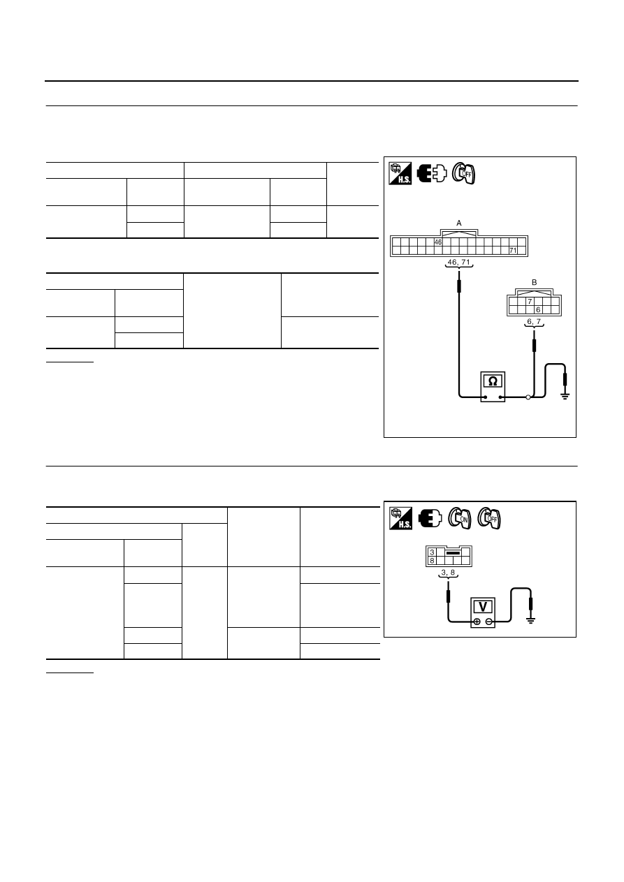
CHECK COMMUNICATION CIRCUIT 1
1.
Turn ignition switch OFF.
2.
Disconnect Intelligent Key unit and power distribution unit connector.
3.
Check continuity between Intelligent Key unit connector and power distribution unit connector.
4.
Check continuity between Intelligent Key unit connector and
ground.
OK or NG
OK
>> Check the condition of harness and connector.
NG
>> Repair or replace harness.
5.
CHECK SIGNAL CIRCUIT
1.
Connect steering lock unit and power distribution unit connector.
2.
Check continuity between steering lock unit connector and ground.
OK or NG
OK
>> Replace steering lock unit.
NG
>> GO TO 6.
A
B
Continuity
Intelligent Key
unit connector
Terminal
Power distribution
unit connector
Terminal
M33
46
M30
6
Yes
71
7
A
Ground
Continuity
Intelligent Key
unit connector
Terminal
M33
46
No
71
PIIB6230E
Terminals
Condition
Voltage (V)
(Approx.)
(+)
(–)
Steering lock
unit connector
Terminal
M35
3
Ground
When turn igni-
tion switch to
START with
Intelligent Key
in the car
Battery voltage
8
0
3
Ignition switch:
OFF
0
8
Battery voltage
PIIB6231E
Нет комментариевНе стесняйтесь поделиться с нами вашим ценным мнением.
Текст