Infiniti M35/M45 Y50. Manual — part 270

INTELLIGENT KEY SYSTEM/ENGINE START FUNCTION
BL-149
C
D
E
F
G
H
J
K
L
M
A
B
BL
6.
CHECK INTELLIGENT KEY FUNCTION
Operate Push-button ignition switch with carrying Intelligent Key to check the power source position can be
turned with all of the Intelligent Keys.
CAUTION:
Operate Push-button ignition switch without depressing the brake pedal.
Can be operated with all of the Intelligent Keys>>GO TO 7.
Can not be operated with particular Intelligent Key>>Check the malfunctioning Intelligent Key. Refer to
124, "INTELLIGENT KEY BATTERY INSPECTION"
Can not be operated with any of the Intelligent Keys>>Perform Diagnostic Procedure. Refer to
"Trouble Diagnosis Symptom Chart 1"
7.
CHECK TURNING TIMING OF POWER SOURCE POSITION 1
Check the power source turning delay time after Push-button ignition switch is pushed. (Approx. 3 sec)
CAUTION:
Operate Push-button ignition switch without depressing the brake pedal.
No delay time exists>>GO TO 8.
Delay time exists>>Perform Diagnostic Procedure. Refer to
BL-178, "Trouble Diagnosis Symptom Chart 2"
8.
CHECK TURNING TIMING OF POWER SOURCE POSITION 2
Check all the Intelligent Keys for power source turning delay time after Push-button ignition switch is pushed
with Intelligent Key inserted into key slot. (Approx. 3 sec)
CAUTION:
Operate Push-button ignition switch without depressing the brake pedal.
No delay time exists>>GO TO 9.
Delay time exists when operated with particular Intelligent Key.>>Perform “C/U INITIALIZATION” referring to
CONSULT-II operation manual IVIS/NVIS NATS. In case that delay time still exists after the initial-
ization, replace the Intelligent Key.
Delay time exists when operated with any of the Intelligent Keys.>>Perform Diagnostic Procedure. Refer to
BL-178, "Trouble Diagnosis Symptom Chart 3"
9.
CHECK ENGINE START FUNCTION
Check that engine can be started with Intelligent Key carried and inserted into the key slot respectively.
Engine can be started.>>GO TO 10.
Engine cannot be started.>>Inspect Trouble Diagnosis Flow Chart for IVIS (NATS). Refer to
ble Diagnoses Flow Chart for IVIS (NATS)"
.
10.
CHECK SECURITY INDICATOR FUNCTION
Check Security Indicator for lighting up under the two conditions below.
●
Security Indicator lights off when Push-button ignition switch is pushed with Intelligent Key inserted into or
pulled out of the key slot.
●
Security Indicator blinks when Intelligent Key is pulled out and Push-button ignition switch is in lock posi-
tion.
Lighting up condition is normal.>>Inspection END.
Lighting up condition is malfunctioning.>>Perform Security Indicator Inspection. Refer to
.
BL-150
INTELLIGENT KEY SYSTEM/ENGINE START FUNCTION
CONSULT-II Functions (INTELLIGENT KEY)
NIS001YK
CONSULT-II can display each diagnostic item using the diagnostic test modes as shown below.
CONSULT-II Inspection Procedure
NIS001YL
CAUTION:
If CONSULT-II is used with no connection CONSULT-II CONVERTER, malfunctions might be detected
in self-diagnosis depending on control unit which performs CAN Communication.
BASIC OPERATION
Refer to
GI-38, "CONSULT-II Start Procedure"
CONSULT-II Application Items
NIS001YM
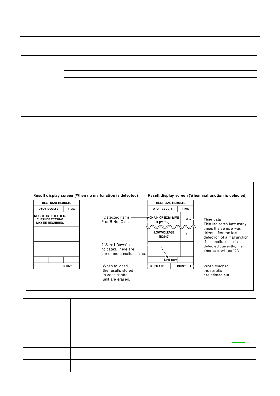
SELF-DIAGNOSTIC RESULTS
How to Read SELF-DIAGNOSTIC RESULTS
Part to be diagnosed
Test item, Diagnosis mode
Description
Intelligent Key
WORK SUPPORT
Changes settings for each function.
SELF-DIAG RESULTS
Intelligent Key unit performs CAN communication diagnosis.
DATA MONITOR
Displays Intelligent Key unit input data in real time.
CAN DIAGNOSTIC SUPPORT
MONITOR
The results of transmit/receive diagnosis of CAN Communication can
be read.
ACTIVE TEST
Operation of electrical loads can be checked by sending driving signal
to then.
ECU PART NUMBER
Displays Intelligent Key unit part No.
PIIB6280E
Suspect Systems
[DTC]
Diagnostic item is detected when...
Repair work
Reference page
CAN COMM CIRCUIT
[U1000]
Malfunction is detected in CAN communication
Perform CAN communi-
cation system inspection
CONTROL UNIT (CAN)
[U1010]
Malfunction is detected in CAN communication caused
by Intelligent Key unit internal malfunction
Replace Intelligent Key
unit.
STRG COMM 1
[B2013]
Communication malfunction with steering lock unit is
detected
Check steering lock unit
STEERING LOCK UNIT
[B2551]
Even if the communication with steering lock unit is
normally performed, the steering lock is malfunctioning
Replace steering lock
unit
INTELLIGENT KEY
[B2552]
Internal malfunction is detected in Intelligent Key unit
Replace Intelligent Key
unit.

INTELLIGENT KEY SYSTEM/ENGINE START FUNCTION
BL-151
C
D
E
F
G
H
J
K
L
M
A
B
BL
CAUTION:
When CAN COMM CIRCUIT [U1000] and CONTROL UNIT (CAN) [U1010] are displayed, give priority to performing trouble diag-
nosis.
DATA MONITOR
IGN POWER CIRCUIT
[B2553]
It continues for 2 seconds or more that ON power sup-
ply input to Intelligent Key unit is excessively low when
the power supply position is in ON position
Check Intelligent Key
unit ON power supply
input
ACC POWER CIRCUIT
[B2554]
It continues for 2 seconds or more that ACC power
supply input to Intelligent Key unit is excessively low
when the power supply position is in ACC or ON posi-
tion
Check Intelligent Key
unit ACC power supply
input
STOP LAMP CIRCUIT
[B2555]
5V or less is detected at both the stop lamp switch sig-
nal input circuit that is input to Intelligent Key unit and
the monitor input before stop lamp switch
Check stop lamp switch
ENG START SW
[B2556]
Condition that push-button ignition switch is pushed is
detected continuously for 100 seconds or more
Check push-button igni-
tion switch
VEHICLE SPEED
[B2557]
Some differences occur on one or more vehicle speed
inputs of Intelligent Key unit
Check vehicle speed sig-
nal
SHIFT POSITION
[B2558]
●
There is a difference between the shift position input
via CAN communication and the P position input by
detent switch
●
Vehicle speed (5 km/h or more) is detected continu-
ously for 10 seconds or more even if the shift posi-
tion is detected in P position when the power supply
position is in ON position
Check shift position input
PDU
[B2559]
Internal malfunction is detected in PDU
Replace PDU
START POW SUP CIRC
[B2560]
Though the engine start operation is not performed,
starter relay in IPDM E/R is ON
Check starter power sup-
ply
LOW VOLTAGE
[B2562]
Battery power supply input to Intelligent Key unit (8.8V
or less) is detected continuously for 1.5 seconds or
more
Check battery low volt-
age
HI VOLTAGE
[B2563]
Battery power supply input to Intelligent Key unit (18V
or more) is detected continuously for 90 seconds or
more
Check for battery high
voltage
NATS MALFUNCTION
[B2590]
Malfunction is detected in immobilizer system
Check (IVIS) NATS trou-
ble diagnosis procedure
Suspect Systems
[DTC]
Diagnostic item is detected when...
Repair work
Reference page
Monitor item
Content
DR REQ SW
Indicates [ON/OFF] condition of door request switch (driver side).
AS REQ SW
Indicates [ON/OFF] condition of door request switch (passenger side).
BD/TR REQ SW
Indicates [ON/OFF] condition of trunk opener request switch.
ON POS
Indicates [ON/OFF] condition of ignition switch in ON position.
ACC POS
Indicates [ON/OFF] condition of ignition switch in ACC position.
DOOR STAT SW
Indicates [ON/OFF] condition of door unlock sensor.
STOP LAMP SW
Indicates [ON/OFF] condition of stop lamp switch.
P RANGE SW
Indicates [ON/OFF] condition of park position switch.
TR CANCEL SW*
Indicates [ON/OFF] condition of trunk cancel switch.
DOOR LOCK SIG*
Indicates [ON/OFF] condition of door lock signal from Intelligent Key remote controller button.
DOOR UNLOCK SIG*
Indicates [ON/OFF] condition of door unlock signal from Intelligent Key remote controller button.
KEYLESS TRUNK*
Indicates [ON/OFF] condition of trunk open signal from Intelligent Key remote controller button.
KEYLESS PANIC*
Indicates [ON/OFF] condition of panic alarm signal from Intelligent Key remote controller button.

BL-152
INTELLIGENT KEY SYSTEM/ENGINE START FUNCTION
*: Select “SELECTION FROM MENU”.
WORK SUPPORT
DOOR SW DR*
Indicates [OPEN/CLOSE] condition of front door switch driver side from BCM via CAN communica-
tion line.
DOOR SW AS*
Indicates [OPEN/CLOSE] condition of front door switch passenger side from BCM via CAN commu-
nication line.
DOOR SW RR*
Indicates [OPEN/CLOSE] condition of rear door switch LH from BCM via CAN communication line.
DOOR SW RL*
Indicates [OPEN/CLOSE] condition of rear door switch RH from BCM via CAN communication line.
DOOR BK SW*
Indicates [OPEN/CLOSE] condition of back door switch from BCM via CAN communication line.
TRUNK SW*
Indicates [OPEN/CLOSE] condition of trunk room lamp switch from BCM via CAN communication
line.
VEHICLE SPEED*
Indicates [km/h] condition of vehicle speed.
Monitor item
Content
Monitor item
Description
CONFIRM KEY FOB ID
It can be checked whether Intelligent Key ID code is registered or not in this mode.
TAKE OUT FROM WINDOW
WARN
Take away warning chime (from window) mode can be changed to operate (ON) or not operate
(OFF) with this mode. The operation mode will be changed when “CHANGE SETT” on CON-
SULT-II screen is touched.
LOW BAT OF KEY FOB WARN
Intelligent Key low battery warning mode can be changed to operate (ON) or not operate (OFF)
with this mode. The operation mode will be changed when “CHANGE SETT” on CONSULT-II
screen is touched.
ANSWER BACK FUNCTION
Hazard and buzzer reminder function mode can be changed to operate (ON) or not operate
(OFF) with this mode. The operation mode will be changed when “CHANGE SETT” on CON-
SULT-II screen is touched.
SELECTIVE UNLOCK FUNC-
TION
Selective unlock function mode can be changed to operate (ON) or not operate (OFF) with this
mode. The operation mode will be changed when “CHANGE SETT” on CONSULT-II screen is
touched.
ANTI KEY LOCK IN FUNCTION
Key reminder function mode can be changed to operate (ON) or not operate (OFF) with this
mode. The operation mode will be changed when “CHANGE SETT” on CONSULT-II screen is
touched.
HORN WITH KEYLESS LOCK
Horn reminder function mode by Intelligent Key button can be changed to operate (ON) or not
operate (OFF) with this mode. The operation mode will be changed when “CHANGE SETT” on
CONSULT-II screen is touched.
HAZARD ANSWER BACK
Hazard reminder function mode can be selected from the following with this mode. The operation
mode will be changed when “CHANGE SETT” on CONSULT-II screen is touched.
●
LOCK ONLY: Door lock operation only
●
UNLOCK ONLY: Door unlock operation only
●
LOCK/UNLOCK: Lock/Unlock operation
●
OFF: Non-operation
ANSWER BACK WITH I-KEY
LOCK
Buzzer reminder function (lock operation) mode by door request switch (driver side and passen-
ger side) can be selected from the following with this mode. The operation mode will be changed
when “CHANGE SETT” on CONSULT-II screen is touched.
●
HORN CHIRP: Sound horn
●
BUZZER: Sound Intelligent Key warning buzzer
●
OFF: Non-operation
ANSWER BACK WITH I-KEY
UNLOCK
Buzzer reminder function (unlock operation) mode by door request switch can be changed to
operate (ON) or not operate (OFF) with this mode.
AUTO RELOCK TIMER
Auto door lock timer mode can select the following with this mode.
●
1 min
●
5 min
●
OFF: Non-operation
Нет комментариевНе стесняйтесь поделиться с нами вашим ценным мнением.
Текст