Infiniti M35/M45 Y50. Manual — part 61
DTC P1815 MANUAL MODE SWITCH
AT-167
D
E
F
G
H
I
J
K
L
M
A
B
AT
DTC P1815 MANUAL MODE SWITCH
PFP:34901
Description
NCS001OT
Manual mode switch is installed in A/T device. It sends manual mode switch, shift up and shift down switch
signals to TCM.
TCM sends the switch signals to combination meters. By CAN communication line. Then manual mode switch
position is indicated on the A/T indicator. For inspection, refer to
AT-186, "A/T INDICATOR CIRCUIT"
.
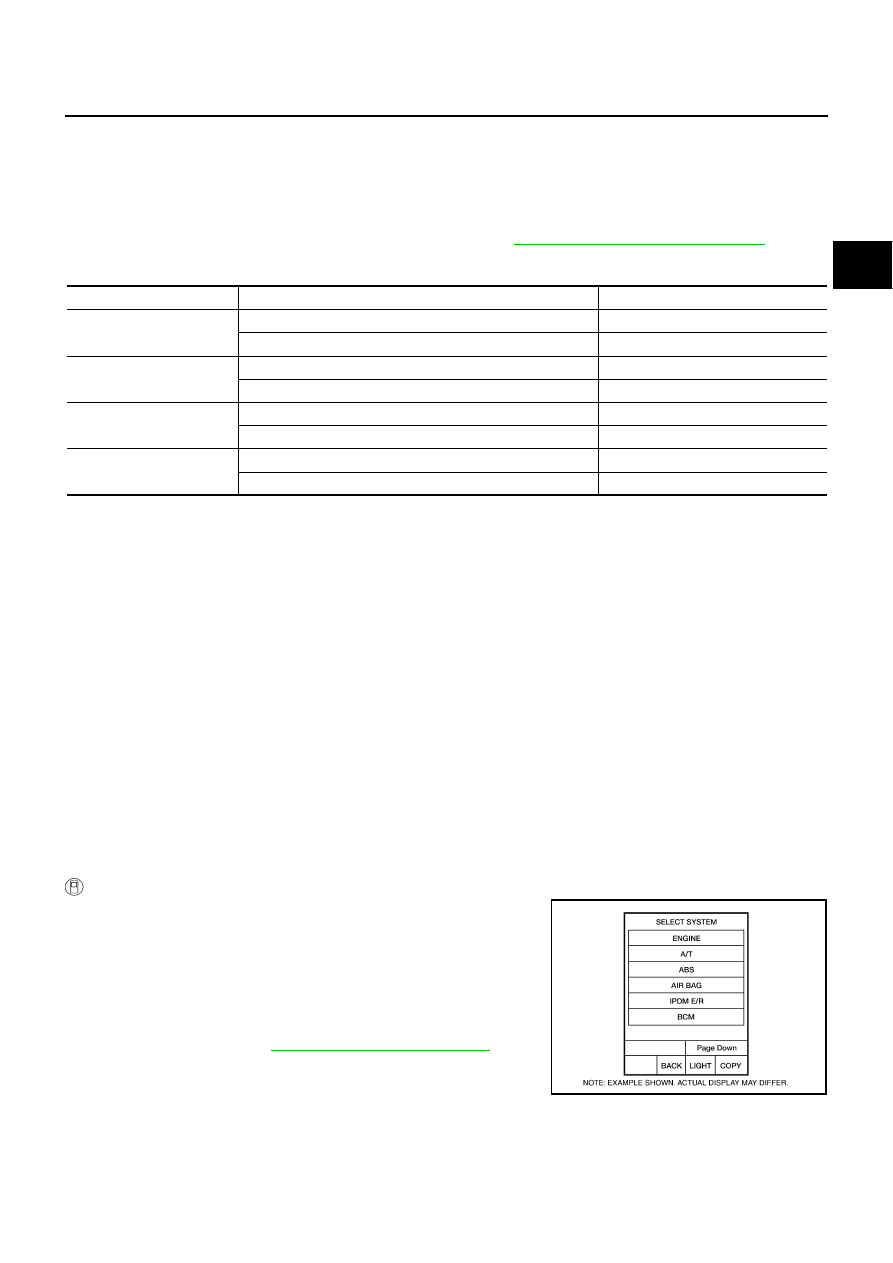
CONSULT-II Reference Value
NCS001OU
On Board Diagnosis Logic
NCS001OV
●
This is not an OBD-II self-diagnostic item.
●
Diagnostic trouble code “P1815 MANU MODE SW/CIRC” with CONSULT-II is detected when TCM moni-
tors Manual mode, Non manual mode, Up or Down switch signal, and detects as irregular when impossi-
ble input pattern occurs 1 second or more.
Possible Cause
NCS001OW
●
Harness or connectors
(These switches circuit is open or shorted.)
●
Manual mode select switch (Into control device)
●
Manual mode position select switch (Into control device)
DTC Confirmation Procedure
NCS001OX
CAUTION:
Always drive vehicle at a safe speed.
NOTE:
If “DTC Confirmation Procedure” has been previously performed, always turn ignition switch OFF and
wait at least 10 seconds before performing the next test.
After the repair, perform the following procedure to confirm the malfunction is eliminated.
WITH CONSULT-II
1.
Turn ignition switch ON.
2.
Select “MAIN SIGNALS” in “DATA MONITOR” mode for “A/T”
with CONSULT-II.
3.
Start engine.
4.
Drive vehicle and maintain the following conditions for at least 2
consecutive seconds.
MANU MODE SW: ON
5.
AT-170, "Diagnostic Procedure"
Item name
Condition
Display Value
MANU MODE SW
Manual shift gate position (neutral)
ON
Other than the above
OFF
NON M-MODE SW
Manual shift gate position
OFF
Other than the above
ON
UP SW LEVER
Selector lever: + side
ON
Other than the above
OFF
DOWN SW LEVER
Selector lever: - side
ON
Other than the above
OFF
BCIA0030E
AT-168
DTC P1815 MANUAL MODE SWITCH
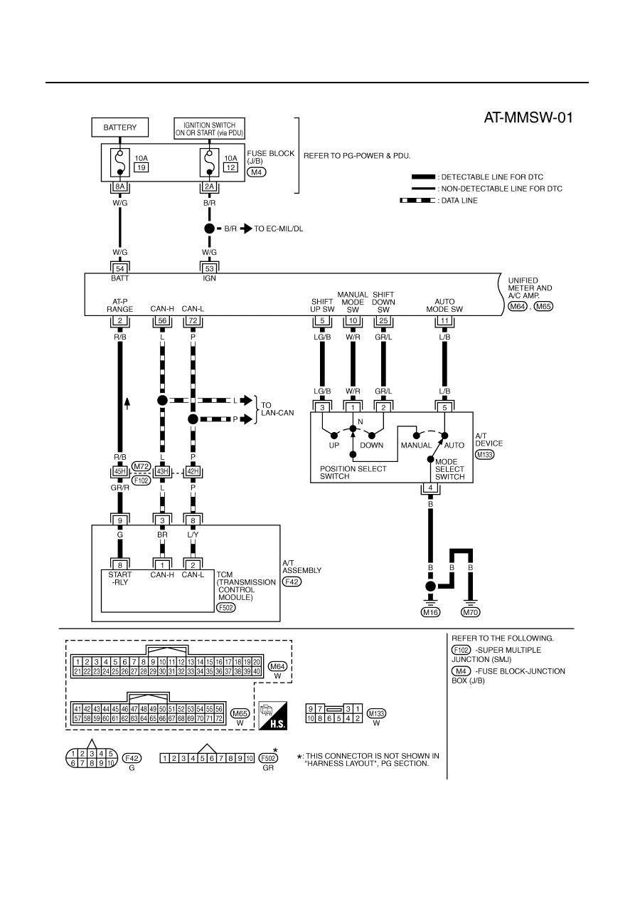
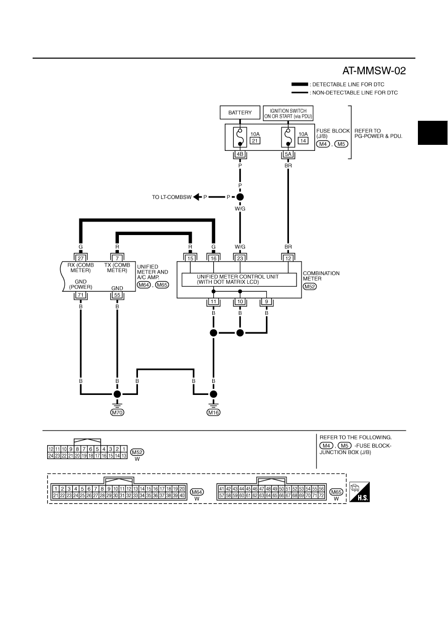
Wiring Diagram — AT — MMSW
NCS001OY
TCWT0347E
DTC P1815 MANUAL MODE SWITCH
AT-169
D
E
F
G
H
I
J
K
L
M
A
B
AT
TCWT0420E
AT-170
DTC P1815 MANUAL MODE SWITCH
TCM terminals and data are reference value. Measured between each terminal and ground.
Diagnostic Procedure
NCS001OZ
1.
CHECK CAN COMMUNICATION LINE
Perform the self-diagnosis. Refer to
AT-92, "SELF-DIAGNOSTIC RESULT MODE"
.
Is a malfunction in the CAN communication indicated in the results?
YES
>> Check CAN communication line. Refer to
AT-105, "DTC U1000 CAN COMMUNICATION LINE"
NO
>> GO TO 2.
2.
CHECK MANUAL MODE SWITCH CIRCUIT
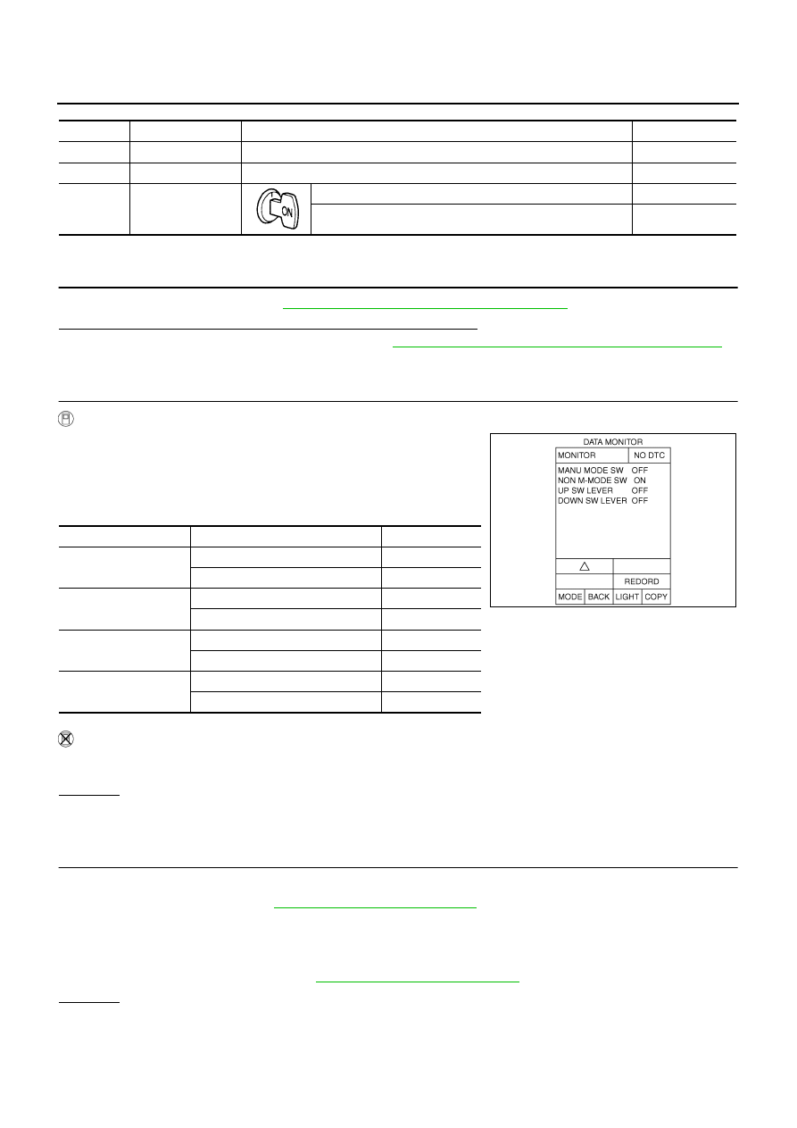
With CONSULT-II
1.
Turn ignition switch ON.
2.
Select “ECU INPUT SIGNALS” in “DATA MONITOR” mode for
“A/T” with CONSULT-II.
3.
Read out ON/OFF switching action of “MANU MODE SW”,
“NON M-MODE SW”, “UP SW LEVER”, “DOWN SW LEVER”.
Without CONSULT-II
Drive vehicle in the manual mode, and confirm that the actual gear position and the meter's indication of the
position mutually coincide when the selector lever is shifted to the “+ (up)” or “- (down)” side (1st
⇔
5th gear).
OK or NG
OK
>> GO TO 4.
NG
>> GO TO 3.
3.
DETECT MALFUNCTIONING ITEM
Check the following.
●
Manual mode switch. Refer to
AT-171, "Component Inspection"
●
Pin terminals for damage or loose connection with harness connector.
●
Open circuit or short to ground or short to power in harness or connector for A/T device (manual mode
switch).
●
Unified meter and A/C amp. Refer to
.
OK or NG
OK
>> GO TO 4.
NG
>> Repair or replace damaged parts.
Terminal
Item
Condition
Data (Approx.)
3
CAN-H
–
–
8
CAN-L
–
–
9
Starter relay
Selector lever in “N”, “P” positions.
Battery voltage
Selector lever in “R”, “D” positions.
0 V
Item name
Condition
Display Value
MANU MODE SW
Manual shift gate position (neutral)
ON
Other than the above
OFF
NON M-MODE SW
Manual shift gate position
OFF
Other than the above
ON
UP SW LEVER
Selector lever: +side
ON
Other than the above
OFF
DOWN SW LEVER
Selector lever: -side
ON
Other than the above
OFF
SCIA4988E
Нет комментариевНе стесняйтесь поделиться с нами вашим ценным мнением.
Текст