Infiniti M35/M45 Y50. Manual — part 332

TROUBLE DIAGNOSIS
BRC-29
[VDC/TCS/ABS]
C
D
E
G
H
I
J
K
L
M
A
B
BRC
FR RH IN SOL
(ON/OFF)
—
×
×
Operation status of all solenoid valve
FR RH OUT SOL
(ON/OFF)
—
×
×
FR LH IN SOL
(ON/OFF)
—
×
×
FR LH OUT SOL
(ON/OFF)
—
×
×
RR RH IN SOL
(ON/OFF)
—
×
×
RR RH OUT SOL
(ON/OFF)
—
×
×
RR LH IN SOL
(ON/OFF)
—
×
×
RR LH OUT SOL
(ON/OFF)
—
×
×
MOTOR RELAY
(ON/OFF)
—
×
×
Motor and motor relay operation
ACTUATOR RLY
(ON/OFF)
—
×
×
Actuator relay operation
ABS WARN LAMP
(ON/OFF)
—
×
×
ABS warning lamp
OFF LAMP
(ON/OFF)
—
×
×
VDC OFF indicator lamp
SLIP LAMP
(ON/OFF)
—
×
×
SLIP indicator lamp
4WD FAIL REQ
(ON/OFF) (Note)
—
—
×
AWD control unit fail-safe signal
SNOW MODE SW
(ON/OFF)
—
—
×
Snow mode switch
BST OPER SIG
—
—
×
Not applied but displayed.
M-MODE SIG
(ON/OFF)
—
—
×
Manual mode activated
EBD SIGNAL
(ON/OFF)
—
—
×
EBD operation
ABS SIGNAL
(ON/OFF)
—
—
×
ABS operation
TCS SIGNAL
(ON/OFF)
—
—
×
TCS operation
VDC SIGNAL
(ON/OFF)
—
—
×
VDC operation
EBD FAIL SIG
(ON/OFF)
—
—
×
EBD fail-safe signal
ABS FAIL SIG
(ON/OFF)
—
—
×
ABS fail-safe signal
TCS FAIL SIG
(ON/OFF)
—
—
×
TCS fail-safe signal
VDC FAIL SIG
(ON/OFF)
—
—
×
VDC fail-safe signal
CRANKING SIG
(ON/OFF)
—
—
×
Crank operation
Item
(Unit)
Data monitor item selection
Display content
ECU INPUT
SIGNALS
MAIN SIGNALS
SELECTION
FROM MENU
BRC-30
[VDC/TCS/ABS]
TROUBLE DIAGNOSIS
×
:Applicable
–:Not applicable
Note: Only AWD models
Active Test
NFS000QI
CAUTION:
●
Do not perform active test while driving vehicle.
●
Make sure to completely bleed air from brake system.
●
The active test cannot be performed with the ABS warning lamp, VDC indicator lamp, SLIP indica-
tor lamp and brake warning lamp are on.
●
ABS warning lamp, VDC OFF indicator lamp, SLIP indicator lamp and brake warning lamp are on
during active test.
●
Erase memory of ICC system after implementing active test. Refer to
OPERATION PROCEDURE
1.
Perform “CONSULT-II Starting Procedure”. Refer to
GI-38, "CONSULT-II Start Procedure"
2.
Touch “SELECT TEST ITEM” is displayed.
3.
Touch necessary test item.
4.
While “MAIN SIGNALS” indication is inverted, touch “START”.
5.
“ACTIVE TEST” screen will be displayed so perform the following test.
NOTE:
●
When active test is performed while depressing the pedal, the pedal depression amount will change.
This is normal. (Only solenoid valve and ABS motor)
●
“TEST IS STOPPED” is displayed 10 seconds after operation start.
●
After “TEST IS STOPPED” is displayed, to perform test again, touch “BACK” and repeat step 3.
USV[FR-RL]
(ON/OFF)
—
—
×
VDC switch-over valve
USV[FL-RR]
(ON/OFF)
—
—
×
HSV[FR-RL]
(ON/OFF)
—
—
×
HSV[FL-RR]
(ON/OFF)
—
—
×
V/R OUTPUT
(ON/OFF)
—
—
×
Solenoid valve relay activated
M/R OUTPUT
(ON/OFF)
—
—
×
Actuator motor and motor relay activated
Item
(Unit)
Data monitor item selection
Display content
ECU INPUT
SIGNALS
MAIN SIGNALS
SELECTION
FROM MENU
SFIA0591E
TROUBLE DIAGNOSIS
BRC-31
[VDC/TCS/ABS]
C
D
E
G
H
I
J
K
L
M
A
B
BRC
TEST ITEMS
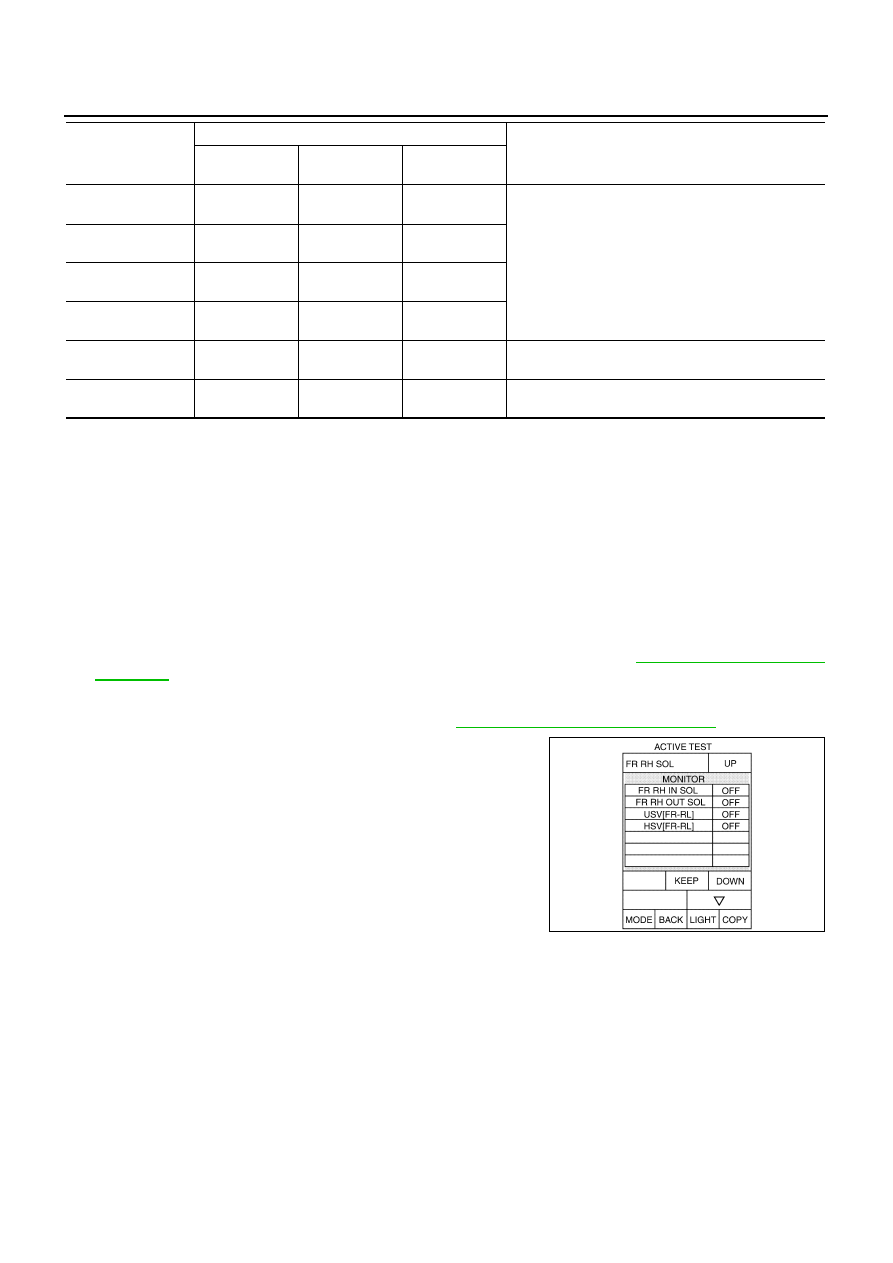
Solenoid Valve
NOTE:
The example shown is for front right wheel. The procedure for the other wheels is the same as given below.
●
When performing an active test of the ABS function, select the
"MAIN SIGNALS" for each test item. In addition, when perform-
ing an active test of the VDC/TCS function, select the item menu
for each test item.
●
For ABS solenoid valve, touch “UP”, “KEEP”, and “DOWN” on
the display screen. For ABS solenoid valve (ACT), touch “UP”,
“ACT UP”, “ACT KEEP” and confirm that solenoid valves (IN,
OUT, USV, HSV) operate as shown in the table below.
*: ON for 1 to 2 seconds after the touch, and then OFF
Note: A brief moment of ON/OFF condition occurs every 20 seconds after ignition switch turned ON. This is not malfunction because it is
an operation for checking.
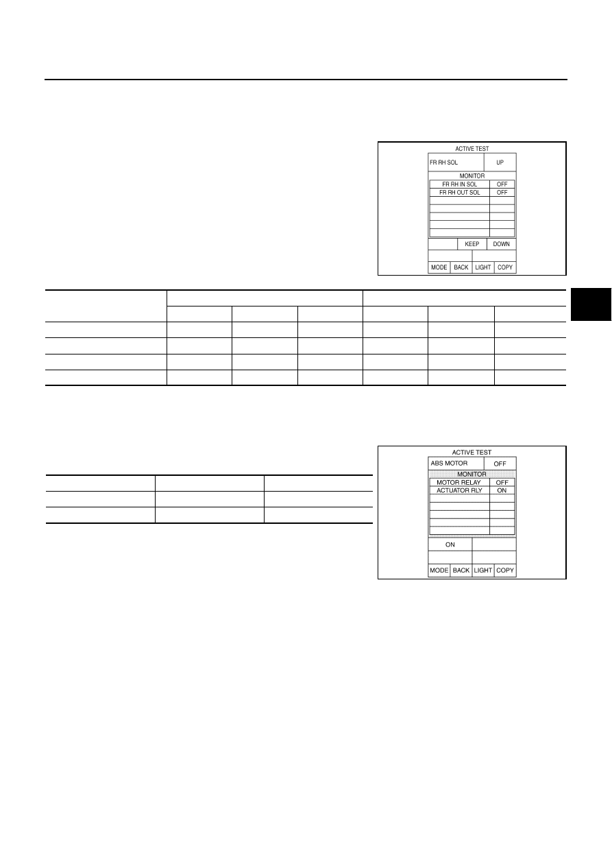
ABS Motor
Touch “ON” and “OFF” on screen. Make sure motor relay and actua-
tor relay operates as shown in table below.
Note: A brief moment of ON/OFF condition occurs every 20 seconds after ignition
switch turned ON. This is not malfunction because it is an operation for checking.
SFIA0678E
Operation
(Note)
ABS solenoid valve
ABS solenoid valve (ACT)
UP
KEEP
DOWN
UP
ACT UP
ACT KEEP
FR RH IN SOL
OFF
ON
ON
OFF
OFF
OFF
FR RH OUT SOL
OFF
OFF
ON*
OFF
OFF
OFF
USV [FR-RL]
OFF
OFF
OFF
OFF
ON
ON
HSV [FR-RL]
OFF
OFF
OFF
OFF
ON*
OFF
Operation
ON
OFF
MOTOR RELAY
ON
OFF
ACTUATOR RLY (Note)
ON
ON
SFIA0593E

BRC-32
[VDC/TCS/ABS]
TROUBLE DIAGNOSIS
For Fast and Accurate Diagnosis
NFS000QJ
PRECAUTIONS FOR DIAGNOSIS
●
Before performing diagnosis, always read General Information (GI) to confirm general precautions. Refer
to
.
●
If steering angle sensor, steering system parts, suspension system parts, ABS actuator and electric unit
(control unit) or tires have been replaced, or if wheel alignment has been adjusted, be sure to adjust neu-
tral position of steering angle sensor before driving. Refer to
BRC-6, "Adjustment of Steering Angle Sen-
●
After diagnosis is finished, be sure to erase memory. Refer to
●
When checking continuity and voltage between unit, be sure to check for disconnection, looseness, bend,
or collapse of connector terminals. If any malfunction is found, repair or replace connector terminals.
●
For intermittent symptoms, possible cause is malfunction in harness, harness connector, or terminals.
Move harness, harness connector, and terminals to check for poor connections.
●
If a circuit tester is used for the check, be careful not to forcibly extend any connector terminal.
●
The following symptoms may be caused by normal operations.
Symptom
Symptom description
Result
Motor operation sound
This is sound of motor inside VDC actuator. Slight sound may occur
during VDC, TCS, and ABS operation.
Normal
Just after engine starts, the motor operating sound may be heard.
This is a normal condition of the system operation check.
System operation check sound
When engine starts, slight “click” sound may be heard from engine
room. This is normal and is part of system operation check.
Normal
VDC/TCS operation
(SLIP indicator lamp ON)
TCS may activate momentarily if wheel speed changes when driving
over location where friction varies, when downshifting, or when fully
depressing accelerator pedal.
Normal
Cancel the VDC/TCS
function for the inspec-
tion on a chassis dyna-
mometer.
When checking speed meter etc. With a 2-wheel-drive chassis dyna-
mometer, vehicle speed is not increased by pressing down on the
accelerator.
ABS operation
(Longer stopping distance)
On roads with low friction, such as snowy roads or gravel roads, vehi-
cles with ABS may require a longer stopping distance. Therefore,
when driving on such roads, avoid overconfidence and keep speed
sufficiently low.
Normal
Insufficient feeling of acceleration
Depending on road conditions, driver may feel that feeling of acceler-
ation is insufficient. This is because traction control, which controls
engine and brakes to achieve optimal traction, has the highest priority
(for safety). As a result, there may be times when acceleration is
slightly less than usual for the same accelerator pedal operation.
Normal
Нет комментариевНе стесняйтесь поделиться с нами вашим ценным мнением.
Текст