Infiniti M35/M45 Y50. Manual — part 330

TROUBLE DIAGNOSIS
BRC-21
[VDC/TCS/ABS]
C
D
E
G
H
I
J
K
L
M
A
B
BRC
Control Unit Input/Output Signal Standard
NFS000RH
REFERENCE VALUE FROM CONSULT-II
CAUTION:
The display shows ABS actuator and electric unit (control unit) calculation data, so a normal value
might be displayed even in the event the output circuit (harness) is open or short-circuited.
Monitor item
Display content
Data monitor
Condition
Reference value in nor-
mal operation
FR LH SENSOR
FR RH SENSOR
RR LH SENSOR
RR RH SENSOR
Wheel speed
Vehicle stopped
0 [km/h (MPH)]
Vehicle running (Note 1)
Nearly matches the
speedometer display
(
±
10 % or less)
STOP LAMP SW
Brake pedal operation
When brake pedal is depressed
ON
When brake pedal is not depressed
OFF
BATTERY VOLT
Battery voltage supplied to the ABS
actuator and electric unit (control unit)
Ignition switch ON
10 – 16 V
GEAR
Gear position determined by TCM
1st gear
2nd gear
3rd gear
4th gear
5th gear
1
2
3
4
5
SLCT LVR POSI
A/T select lever position
P position
R position
N position
D position
P
R
N
D
OFF SW
VDC OFF switch
VDC OFF switch :ON
(When VDC OFF indicator lamp is ON)
ON
VDC OFF switch :OFF
(When VDC OFF indicator lamp is OFF)
OFF
YAW RATE SEN
Yaw rate detected by yaw rate/side G
sensor
When vehicle stop
Approx. 0 d/s
When vehicle turning
(–75 to 75 d/s)
4WD MODE MON
(Note 2)
AWD activated
Engine running
AUTO
ACCEL POS SIG
Throttle actuator opening/closing is dis-
played (linked with accelerator pedal)
Accelerator pedal not depressed
(Engine stopped)
0 %
Depress accelerator pedal
(Engine stopped)
0 - 100 %
SIDE G-SENSOR
Transverse G detected by side G sensor
Vehicle stopped
Approx. 0 m/s
2
Vehicle turning right
Negative value
(m/s
2
)
Vehicle turning left
Positive value
(m/s
2
)
STR ANGLE SIG
Steering angle detected by steering
angle sensor
Straight-ahead
Approx. 0
°
Steering wheel turned
–720 to 720
°
PRESS SENSOR
Brake fluid pressure detected by pres-
sure sensor
With ignition switch turned ON and brake
pedal released
Approx. 0 bar
With ignition switch turned ON and brake
pedal depressed
–40 to 300 bar
ENGINE RPM
Engine speed
With engine stopped
0 rpm
Engine running
Almost in accordance
with tachometer display

BRC-22
[VDC/TCS/ABS]
TROUBLE DIAGNOSIS
FLUID LEV SW
Brake fluid level switch
Brake fluid level switch ON
ON
Brake fluid level switch OFF
OFF
PARK BRAKE SW
Parking brake switch
Parking brake switch is active
ON
Parking brake switch is inactive
OFF
FR RH IN SOL
FR RH OUT SOL
FR LH IN SOL
FR LH OUT SOL
RR RH IN SOL
RR RH OUT SOL
RR LH IN SOL
RR LH OUT SOL
Operation status of all solenoid valve
Actuator (solenoid valve) is active
(“ACTIVE TEST” with CONSULT-II) or
actuator relay is inactive (in fail-safe
mode)
ON
When the actuator (solenoid valve) is not
active and actuator relay is active (igni-
tion switch ON)
OFF
MOTOR RELAY
Motor and motor relay operation
When the motor relay and motor are
operating
ON
When the motor relay and motor are not
operating
OFF
ACTUATOR RLY
(Note 3)
Actuator relay operation
When the actuator relay is operating
ON
When the actuator relay is not operating
OFF
ABS WARN LAMP
ABS warning lamp
(Note 4)
When ABS warning lamp is ON
ON
When ABS warning lamp is OFF
OFF
OFF LAMP
VDC OFF indicator lamp
(Note 4)
When VDC OFF indicator lamp is ON
ON
When VDC OFF indicator lamp is OFF
OFF
SLIP LAMP
SLIP indicator lamp
(Note 4)
When SLIP indicator lamp is ON
ON
When SLIP indicator lamp is OFF
OFF
4WD FAIL REQ
(Note 2)
AWD control unit fail-safe signal
When AWD control unit is fail-safe mode
ON
When AWD control unit is normal
OFF
SNOW MODE SW
Snow mode switch
When snow mode switch is ON
ON
When snow mode switch is OFF
OFF
BST OPER SIG
Not applied but displayed
—
OFF
M-MODE SIG
Manual mode operation
When the manual mode is active
ON
When the manual mode is inactive
OFF
EBD SIGNAL
EBD operation
EBD is active
ON
EBD is inactive
OFF
ABS SIGNAL
ABS operation
ABS is active
ON
ABS is inactive
OFF
TCS SIGNAL
TCS operation
TCS is active
ON
TCS is inactive
OFF
VDC SIGNAL
VDC operation
VDC is active
ON
VDC is inactive
OFF
EBD FAIL SIG
EBD fail-safe signal
In EBD fail-safe
ON
EBD is normal
OFF
ABS FAIL SIG
ABS fail-safe signal
In ABS fail-safe
ON
ABS is normal
OFF
TCS FAIL SIG
TCS fail-safe signal
In TCS fail-safe
ON
TCS is normal
OFF
Monitor item
Display content
Data monitor
Condition
Reference value in nor-
mal operation
TROUBLE DIAGNOSIS
BRC-23
[VDC/TCS/ABS]
C
D
E
G
H
I
J
K
L
M
A
B
BRC
Note 1: Confirm tire pressure is normal.
Note 2: Only AWD models.
Note 3: A brief moment of ON/OFF condition occurs every 20 seconds after ignition switch turned ON. This is not malfunction because it
is an operation for checking.
Note 4: On and off timing for warning lamp and indicator lamp. Refer to
BRC-33, "ON and OFF Timing for Warning Lamp and Indicator
CONSULT-II Functions (ABS)
NFS000QF
CONSULT-II MAIN FUNCTION
CONSULT-II can display each diagnostic item using the diagnostic test modes shown following.
CONSULT-II SETTING PROCEDURE
Refer to
GI-38, "CONSULT-II Start Procedure"
.
VDC FAIL SIG
VDC fail-safe signal
In VDC fail-safe
ON
VDC is normal
OFF
CRANKING SIG
Crank operation
Crank is active
ON
Crank is inactive
OFF
USV[FR-RL]
USV[FL-RR]
HSV[FR-RL]
HSV[FL-RR]
(Note 3)
VDC switch-over valve
When actuator (switch-over valve) is
active (“ACTIVE TEST” with CONSULT-
II) or actuator relay is inactive (when in
fail-safe mode)
ON
When actuator (switch-over valve) is not
active and actuator relay is active (igni-
tion switch ON)
OFF
V/R OUTPUT
(Note 3)
Solenoid valve relay activated
When the solenoid valve relay is active
ON
When the solenoid valve relay is not
active (in the fail-safe mode)
OFF
M/R OUTPUT
Actuator motor and motor relay activated
When the actuator motor and motor relay
are active (“ACTIVE TEST” with CON-
SULT-II)
ON
When the actuator motor and motor relay
are inactive
OFF
Monitor item
Display content
Data monitor
Condition
Reference value in nor-
mal operation
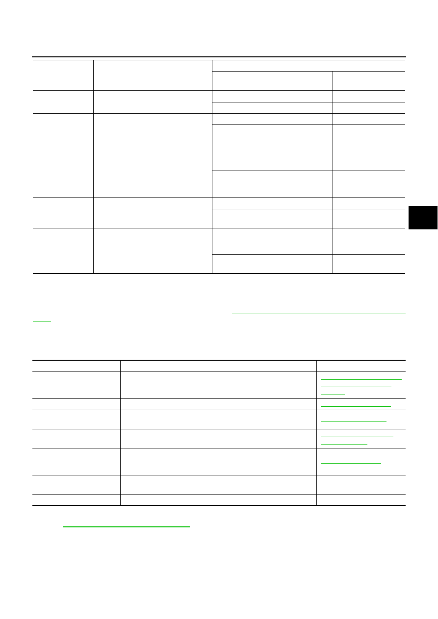
Diagnostic test mode
Function
Reference
WORK SUPPORT
This mode enables a technician to adjust some devices faster and
more accurately by following the indications on CONSULT-II.
BRC-6, "Adjustment of Steer-
ing Angle Sensor Neutral
Position"
SELF-DIAG RESULTS
Self-diagnostic results can be read and erased quickly.
DATA MONITOR
Input/Output data in the ABS actuator and electric unit (control unit)
can be read.
CAN DIAG SUPPORT MNTR
The results of transmit/receive diagnosis of communication can be
read.
LAN-44, "CAN Diagnostic
Support Monitor"
ACTIVE TEST
Diagnostic Test Mode in which CONSULT-II drives some actuators
apart from the ABS actuator and electric unit (control unit) and also
shifts some parameters in a specified range.
FUNCTION TEST
Performed by CONSULT-II instead of a technician to determine
whether each system is “OK” or “NG”.
—
ECU PART NUMBER
ABS actuator and electric unit (control unit) part number can be read.
—
BRC-24
[VDC/TCS/ABS]
TROUBLE DIAGNOSIS
Self-Diagnosis
NFS000QG
OPERATION PROCEDURE
1.
Turn ignition switch OFF.
2.
Perform “CONSULT-II Starting Procedure”. Refer to
GI-38, "CONSULT-II Start Procedure"
3.
Turn ignition switch ON.
4.
Start engine and drive vehicle at 30 km/h (19 MPH) or more for approximately 1 minute.
5.
After stopping vehicle, with the engine running, touch “ABS”, “SELF-DIAG RESULTS” in order on the
CONSULT-II screen.
CAUTION:
If “START (NISSAN BASED VHCL)” is touched immediately after starting engine or turning on the
ignition switch, “ABS” might not be displayed in the “SELECT SYSTEM” screen. In this case,
repeat the operation from step 1.
6.
The self-diagnostic results are displayed. (Touch “PRINT” to print out self-diagnostic results, if necessary.)
●
Check ABS warning lamp, VDC OFF indicator lamp and SLIP indicator lamp if “NO FAILURE” is dis-
played. Refer to
BRC-50, "Warning Lamp and Indicator Lamp Circuit"
7.
Perform the appropriate inspection from display item list, and repair or replace the malfunctioning compo-
nent.Refer to
8.
Start engine and drive vehicle at 30 km/h (19 MPH) or more for approximately 1 minute.
CAUTION:
When the wheel sensor malfunctions, after inspecting the wheel sensor system, the ABS warning
lamp, VDC OFF indicator lamp, SLIP indicator lamp and brake warning lamp will not turn off even
when the system is normal unless the vehicle is driving at approximately 30 km/h (19 MPH) or
more for approximately 1 minute.
ERASE MEMORY
1.
Turn ignition switch OFF.
2.
Start engine and touch “ABS”, “SELF-DIAG RESULTS”, “ERASE MEMORY” in order on the CONSULT-II
screen to erase the diagnostic memory.
If “ABS” is not indicated, go to
GI-39, "CONSULT-II Data Link Connector (DLC) Circuit"
CAUTION:
If the diagnostic memory is not erased, re-perform the operation from step 4.
3.
Perform self-diagnosis again, and make sure that diagnostic memory is erased.
4.
Drive vehicle at 30 km/h (19 MPH) or more for approximately 1 minute as the final inspection, and make
sure that the ABS warning lamp, VDC OFF indicator lamp, SLIP indicator lamp and brake warning lamp
turn off.
NOTE:
●
Brake warning lamp will turn on in case of parking brake operation (when switch is ON) or of brake fluid
level switch operation (when brake fluid is insufficient).
●
VDC OFF switch should not stay "ON" position.
Нет комментариевНе стесняйтесь поделиться с нами вашим ценным мнением.
Текст