Infiniti M35/M45 Y50. Manual — part 427
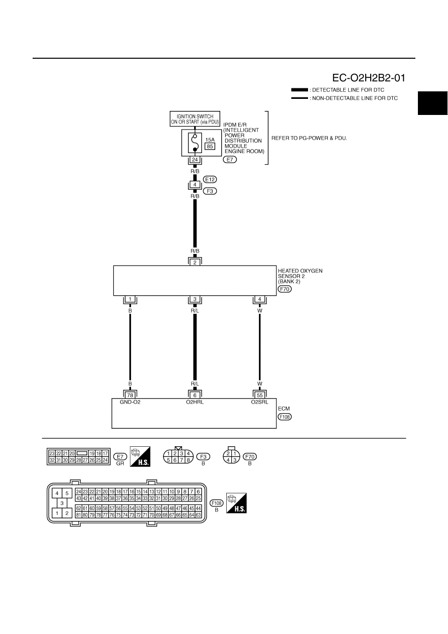
DTC P0037, P0038, P0057, P0058 HO2S2 HEATER
EC-181
[VQ35DE]
C
D
E
F
G
H
I
J
K
L
M
A
EC
BANK 2
TBWT1471E
EC-182
[VQ35DE]
DTC P0037, P0038, P0057, P0058 HO2S2 HEATER
Specification data are reference values and are measured between each terminal and ground.
CAUTION:
Do not use ECM ground terminals when measuring input/output voltage. Doing so may result in dam-
age to the ECM's transistor. Use a ground other than ECM terminals, such as the ground.
Diagnostic Procedure
NBS004UD
1.
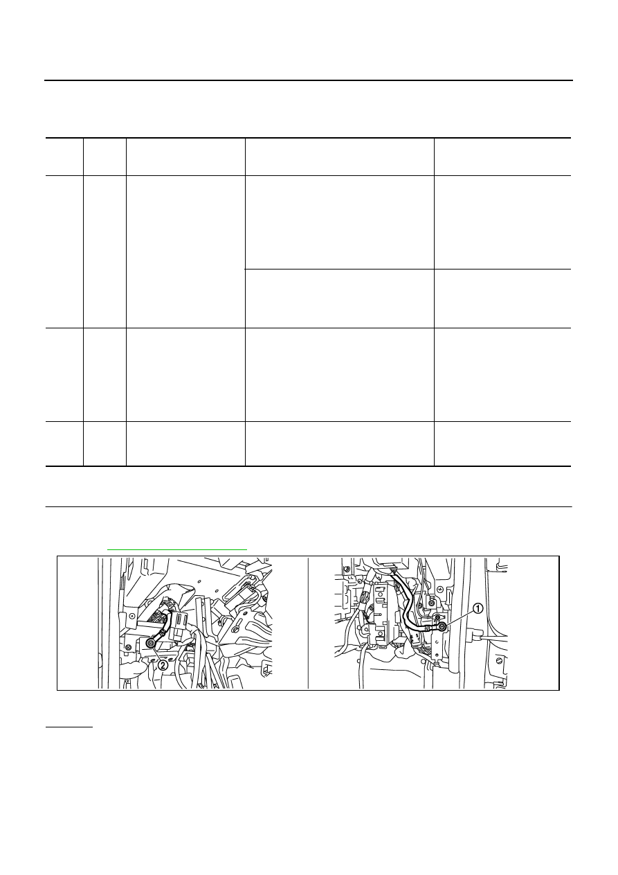
CHECK GROUND CONNECTIONS
1.
Turn ignition switch OFF.
2.
Loosen and retighten two ground screws on the body.
Refer to
OK or NG
OK
>> GO TO 2.
NG
>> Repair or replace ground connections.
TER-
MINAL
NO.
WIRE
COLOR
ITEM
CONDITION
DATA (DC Voltage)
6
R/L
Heated oxygen sensor 2
heater (bank 2)
[Engine is running]
●
Engine speed: Below 3,600 rpm after the
following conditions are met
–
Engine: After warming up
–
Keeping the engine speed between 3,500
and 4,000 rpm for 1 minute and at idle for 1
minute under no load
0 - 1.0V
[Ignition switch: ON]
●
Engine stopped
[Engine is running]
●
Engine speed: Above 3,600 rpm
BATTERY VOLTAGE
(11 - 14V)
55
W
Heated oxygen sensor 2
(bank 2)
[Engine is running]
●
Revving engine from idle to 3,000 rpm
quickly after the following conditions are met
–
Engine: After warming up
–
Keeping the engine speed between 3,500
and 4,000 rpm for 1 minute and at idle for 1
minute under no load
0 - Approximately 1.0V
78
B
Sensor ground
(Heated oxygen sensor)
[Engine is running]
●
Warm-up condition
●
Idle speed
Approximately 0V
1.
Body ground M70
2.
Body ground M16
PBIB2782E
DTC P0037, P0038, P0057, P0058 HO2S2 HEATER
EC-183
[VQ35DE]
C
D
E
F
G
H
I
J
K
L
M
A
EC
2.
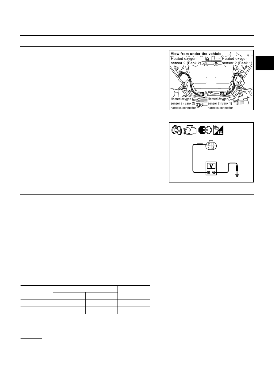
CHECK HO2S2 POWER SUPPLY CIRCUIT
1.
Disconnect heated oxygen sensor 2 harness connector.
2.
Turn ignition switch ON.
3.
Check voltage between HO2S2 terminal 2 and ground with
CONSULT-II or tester.
OK or NG
OK
>> GO TO 4.
NG
>> GO TO 3.
3.
DETECT MALFUNCTIONING PART
Check the following.
●
Harness connectors E12, F3
●
IPDM E/R connector E7
●
15A fuse
●
Harness for open or short between heated oxygen sensor 2 and fuse
>> Repair open circuit or short to ground or short to power in harness or connectors.
4.
CHECK HO2S2 OUTPUT SIGNAL CIRCUIT FOR OPEN AND SHORT
1.
Turn ignition switch OFF.
2.
Disconnect ECM harness connector.
3.
Check harness continuity between ECM terminal and HO2S2 terminal as follows.
Refer to Wiring Diagram.
4.
Also check harness for short to ground and short to power.
OK or NG
OK
>> GO TO 5.
NG
>> Repair open circuit or short to ground or short to power in harness or connectors.
PBIB1576E
Voltage: Battery voltage
PBIA9576J
DTC
Terminals
Bank
ECM
Sensor
P0037, P0038
25
3
1
P0057, P0058
6
3
2
Continuity should exist.
EC-184
[VQ35DE]
DTC P0037, P0038, P0057, P0058 HO2S2 HEATER
5.
CHECK HEATED OXYGEN SENSOR 2 HEATER
Refer to
EC-184, "Component Inspection"
OK or NG
OK
>> GO TO 6.
NG
>> Replace malfunctioning heated oxygen sensor 2.
6.
CHECK INTERMITTENT INCIDENT
Refer to
EC-153, "TROUBLE DIAGNOSIS FOR INTERMITTENT INCIDENT"
.
>> INSPECTION END
Component Inspection
NBS004UE
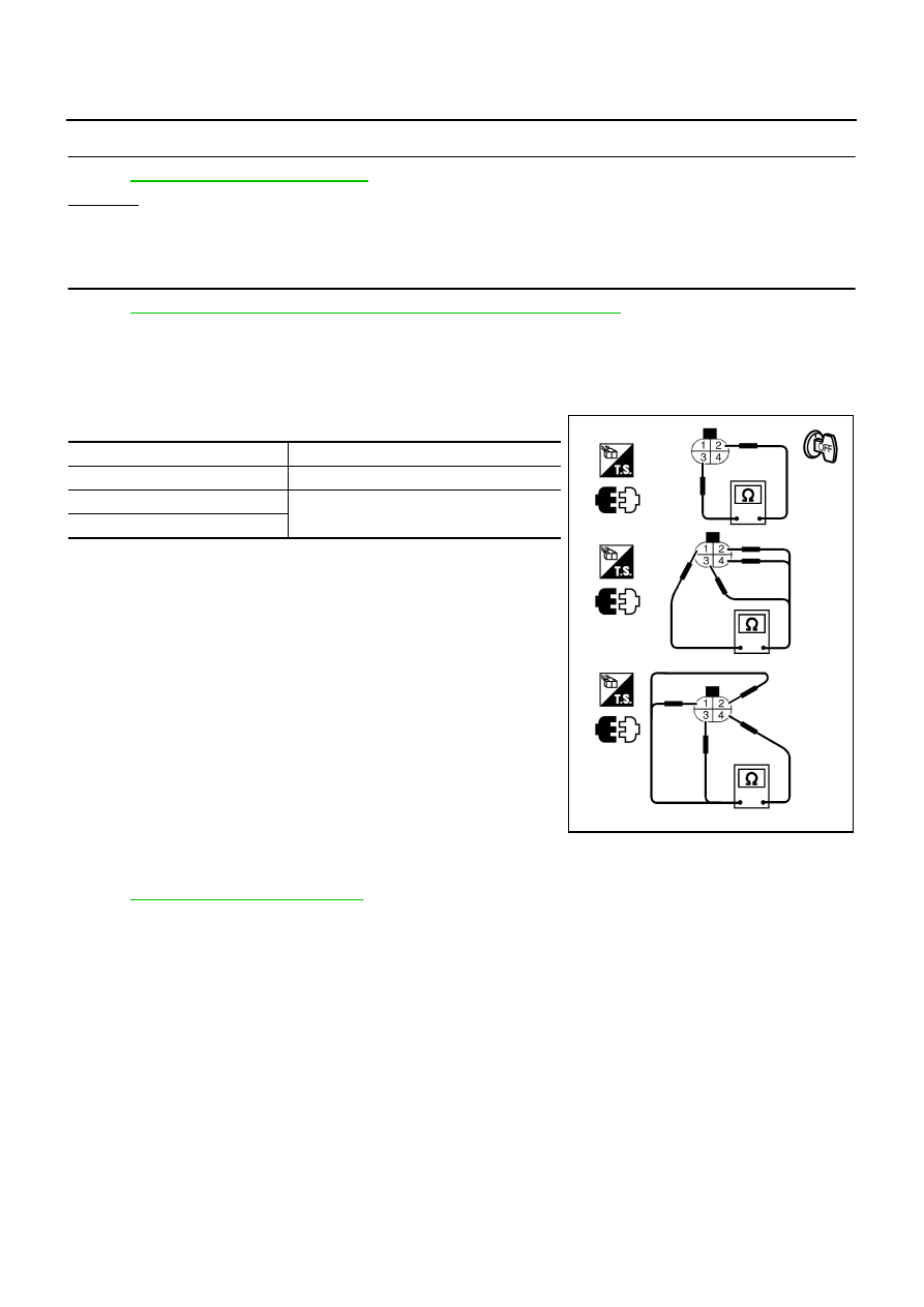
HEATED OXYGEN SENSOR 2 HEATER
1.
Check resistance between HO2S2 terminals as follows.
2.
If NG, replace heated oxygen sensor 2.
CAUTION:
●
Discard any heated oxygen sensor which has been dropped
from a height of more than 0.5 m (19.7 in) onto a hard sur-
face such as a concrete floor; use a new one.
●
Before installing new oxygen sensor, clean exhaust system
threads using Oxygen Sensor Thread Cleaner tool J-43897-
18 or J-43897-12 and approved anti-seize lubricant.
Removal and Installation
NBS004UF
HEATED OXYGEN SENSOR 2
Refer to
.
Terminal No.
Resistance
2 and 3
3.4 - 4.4
Ω
at 25
°
C (77
°
F)
1 and 2, 3, 4
∞
Ω
(Continuity should not exist)
4 and 1, 2, 3
PBIB3344E
Нет комментариевНе стесняйтесь поделиться с нами вашим ценным мнением.
Текст