Infiniti M35/M45 Y50. Manual — part 781
PRECAUTIONS
FSU-21
[AWD]
C
D
F
G
H
I
J
K
L
M
A
B
FSU
[AWD]
PRECAUTIONS
PFP:00001
Caution
NES000IM
●
When installing rubber bushings, the final tightening must be carried out under unladen conditions with
tires on ground. Oil might shorten the life of rubber bushings. Be sure to wipe off any spilled oil.
–
Unladen conditions mean that fuel, engine coolant and lubricant are full. Spare tire, jack, hand tools and
mats are in designated positions.
●
After servicing suspension parts, be sure to check wheel alignment.
●
Self-lock nuts are not reusable. Always use new ones when installing. Since new self-lock nuts are pre-
oiled, tighten as they are.
FSU-22
[AWD]
PREPARATION
PREPARATION
PFP:00002
Special Service Tools [SST]
NES000IN
The actual shapes of Kent-Moore tools may differ from those of special service tools illustrated here.
Commercial Service Tools
NES000IO
Tool number
(Kent-Moore No.)
Tool name
Description
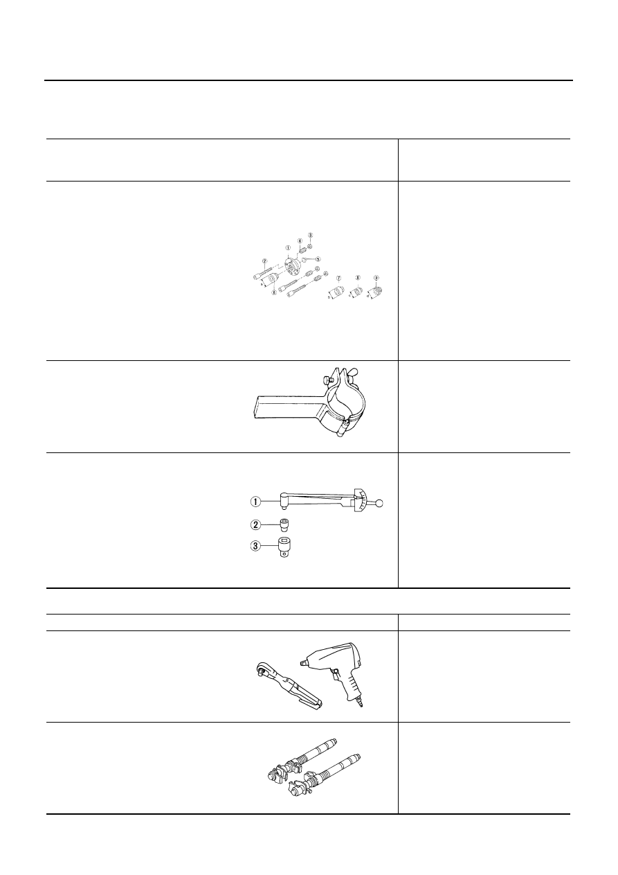
KV991040S0
(
—
)
CCK gauge attachment
1. Plate
2. Guide bolt
3. Nut
4. Spring
5. Center plate
6. KV99104020 Adapter A
a: 72 mm (2.83 in) dia.
7. KV99104030 Adapter B
b: 65 mm (2.56 in) dia.
8. KV99104040 Adapter C
c: 57 mm (2.24 in) dia.
9. KV99104050 Adapter D
d: 53.4 mm (2.102 in) dia.
Measuring wheel alignment
ST35652000
(
—
)
Strut attachment
Disassembling and assembling shock
absorber
ST3127S000
(See J-25765-A)
Preload Gauge
1. GG91030000
(J-25765-A)
Torque wrench
2. HT62940000
(
—
)
Socket adapter
3. HT62900000
(
—
)
Socket adapter
Measuring rotating torque of ball joint
S-NT498
ZZA0807D
NT124
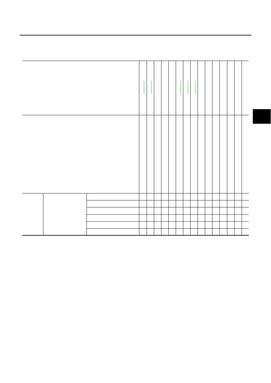
Tool name
Description
Power tool
●
Removing wheel nuts
●
Removing torque member fixing bolts
●
Removing undercover
●
Removing front suspension compo-
nents parts
●
Removing hub lock nut
Spring compressor
Removing and installing coil spring
PBIC0190E
S-NT717
NOISE, VIBRATION AND HARSHNESS (NVH) TROUBLESHOOTING
FSU-23
[AWD]
C
D
F
G
H
I
J
K
L
M
A
B
FSU
NOISE, VIBRATION AND HARSHNESS (NVH) TROUBLESHOOTING
PFP:00003
NVH Troubleshooting Chart
NES000IP
Use chart below to help you find the cause of the symptom. If necessary, repair or replace these parts.
×
: Applicable
Reference page
—
—
—
NVH
in
PR s
e
c
tio
n
NVH in
RFD s
e
c
tio
n
NVH
in
F
A
X
a
n
d
FSU s
e
c
ti
o
n
NVH i
n
W
T
s
e
c
tio
n
NVH
in
F
A
X s
e
c
ti
o
n
NVH
in
BR s
e
c
tio
n
NVH
in
PS s
e
c
tio
n
Possible cause and SUSPECTED PARTS
Im
pr
o
per
i
n
st
al
la
ti
on
,
lo
osen
ess
S
tr
u
t d
e
fo
rm
at
ion,
d
a
m
age
or
d
e
fl
ec
ti
on
Bus
h
ing or
m
oun
ti
ng det
er
io
ra
ti
on
P
a
rt
s
in
te
rf
e
re
n
c
e
Spr
ing f
a
ti
gue
Sus
pens
io
n l
o
o
s
ene
ss
In
co
rr
ect
w
h
e
e
l al
ignm
en
t
S
ta
b
ili
z
er
bar
f
a
ti
g
u
e
PROPELL
E
R SHAF
T
DIFFERENTIAL
FRONT AXLE AND FRO
N
T
SUSPENSION
ROAD W
H
EEL
D
R
IV
E
SH
AF
T
BRAKES
STEERING
Symptom
FRONT SUSPENSION
Noise
×
×
×
×
×
×
×
×
×
×
×
×
×
Shake
×
×
×
×
×
×
×
×
×
×
×
Vibration
×
×
×
×
×
×
×
×
×
Shimmy
×
×
×
×
×
×
×
×
×
Judder
×
×
×
×
×
×
×
Poor quality ride or handling
×
×
×
×
×
×
×
×
×
FSU-24
[AWD]
FRONT SUSPENSION ASSEMBLY
FRONT SUSPENSION ASSEMBLY
PFP:54010
On-Vehicle Inspection
NES000IQ
Make sure the mounting conditions (looseness, back lash) of each component and component conditions
(wear, damage) are normal.
INSPECTION OF UPPER LINK BALL JOINT END PLAY
1.
Set front wheels in a straight-ahead position. Do not depress brake pedal.
2.
Place an iron bar or similar tool between transverse link and steering knuckle.
3.
Measure axial end play by prying it up and down.
CAUTION:
Be careful not to damage ball joint boot. Do not damage the installation position by applying
excessive force.
SHOCK ABSORBER INSPECTION
Check for oil leakage, damage and breakage of installation positions.
Wheel Alignment Inspection
NES000IR
DESCRIPTION
Measure wheel alignment under unladen conditions.
NOTE:
“Unladen conditions” means that fuel, engine coolant, and lubricant are full. Spare tire, jack, hand tools and
mats are in designated positions.
PRELIMINARY CHECK
Check the following:
1.
Check tires for improper air pressure and wear.
2.
Check road wheels for runout. Refer to
3.
Check wheel bearing axial end play. Refer to
FAX-5, "WHEEL BEARING INSPECTION"
4.
Check transverse link ball joint axial end play. Refer to
FSU-32, "INSPECTION AFTER REMOVAL"
5.
Check shock absorber operation.
6.
Check each mounting part of axle and suspension for looseness and deformation.
7.
Check each of suspension member, shock absorber, upper link and transverse link for cracks, deforma-
tion and other damage.
8.
Check vehicle height (posture).
GENERAL INFORMATION AND RECOMMENDATIONS
●
A four-wheel thrust alignment should be performed.
–
This type of alignment is recommended for any NISSAN/INFINITI vehicle.
–
The four-wheel “thrust” process helps ensure that the vehicle is properly aligned and the steering wheel is
centered.
–
The alignment rack itself should be capable of accepting any NISSAN/INFINITI vehicle.
–
The rack should be checked to ensure that it is level.
●
Make sure the machine is properly calibrated.
–
Your alignment equipment should be regularly calibrated in order to give correct information.
–
Check with the manufacturer of your specific equipment for their recommended Service/Calibration
Schedule.
Axial end play
: 0 mm (0 in)
Нет комментариевНе стесняйтесь поделиться с нами вашим ценным мнением.
Текст