Infiniti M35/M45 Y50. Manual — part 779
COIL SPRING AND SHOCK ABSORBER
FSU-13
[2WD]
C
D
F
G
H
I
J
K
L
M
A
B
FSU
CAUTION:
●
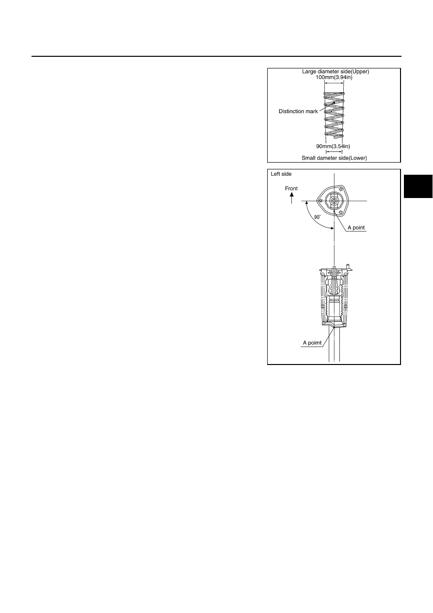
Install coil spring as shown in the figure with large diame-
ter side [100 mm (3.94 in)] up and small diameter side [90
mm (3.54 in)] down. (Distinction marks are 4.75 and 5.75
turn from the lower side end.)
●
Be sure a spring compressor is securely attached to coil
spring. Compress coil spring.
3.
Apply soapy water to bound bumper. Insert bound bumper into
shock absorber mounting bracket, and then install it to shock
absorber together with rubber seat.
CAUTION:
Do not use machine oil.
●
Install shock absorber mounting bracket as shown in the fig-
ure.
CAUTION:
●
Coil spring is securely seated in spring mounting groove
of rubber seat.
●
The bottom part of spring should be at the position of A
point of spring seat.
4.
Secure piston rod tip so that piston rod does not turn, then
tighten piston rod lock nut with specified torque.
5.
Gradually release a spring compressor, and remove coil spring.
CAUTION:
Loosen while making sure coil spring attachment position
does not move.
6.
Remove the strut attachment from shock absorber.
SEIA0661E
SEIA0662E
FSU-14
[2WD]
TRANSVERSE LINK
TRANSVERSE LINK
PFP:54500
Removal and Installation
NES000IG
REMOVAL
1.
Remove tires from vehicle with a power tool.
2.
Remove undercover with a power tool.
3.
Remove the mounting nut on the upper side of stabilizer connecting rod with a power tool, and then
remove stabilizer connecting rod from transverse link.
4.
Separate steering gear assembly and lower joint. Refer to
.
5.
6.
Remove the mounting nut and bolt on the lower side of shock absorber with a power tool, and then
remove shock absorber from transverse link.
7.
Remove transverse link from steering knuckle. Refer to
FAX-5, "Removal and Installation"
8.
Set jack under front suspension member.
9.
Remove the mounting bolts of member bracket, and then remove member bracket from front suspension
member with a power tool. Refer to
10. Remove the mounting nut and bolts of member stay, and then remove member stay from front suspension
member and vehicle with a power tool.
11. Remove the mounting nut of front suspension member with a power tool. Refer to
.
12. Gradually lower the suspension member to the position where transverse link mounting bolts is remove.
CAUTION:
Be careful not to lower it too far. (Do not overload the links)
13. Remove mounting nut and bolts, and then remove transverse link from vehicle.
INSPECTION AFTER REMOVAL
Visual Inspection
●
Check transverse link and bushing for deformation, cracks or damage. Replace it if a malfunction is
detected.
●
Check ball joint boot for cracks or other damage, and also for grease leakage. Replace it if a malfunction
is detected.
Ball Joint Inspection
Manually move ball stud to confirm it moves smoothly with no binding.
Swing Torque Inspection
NOTE:
Before measurement, move ball stud at least ten times by hand to check for smooth movement.
●
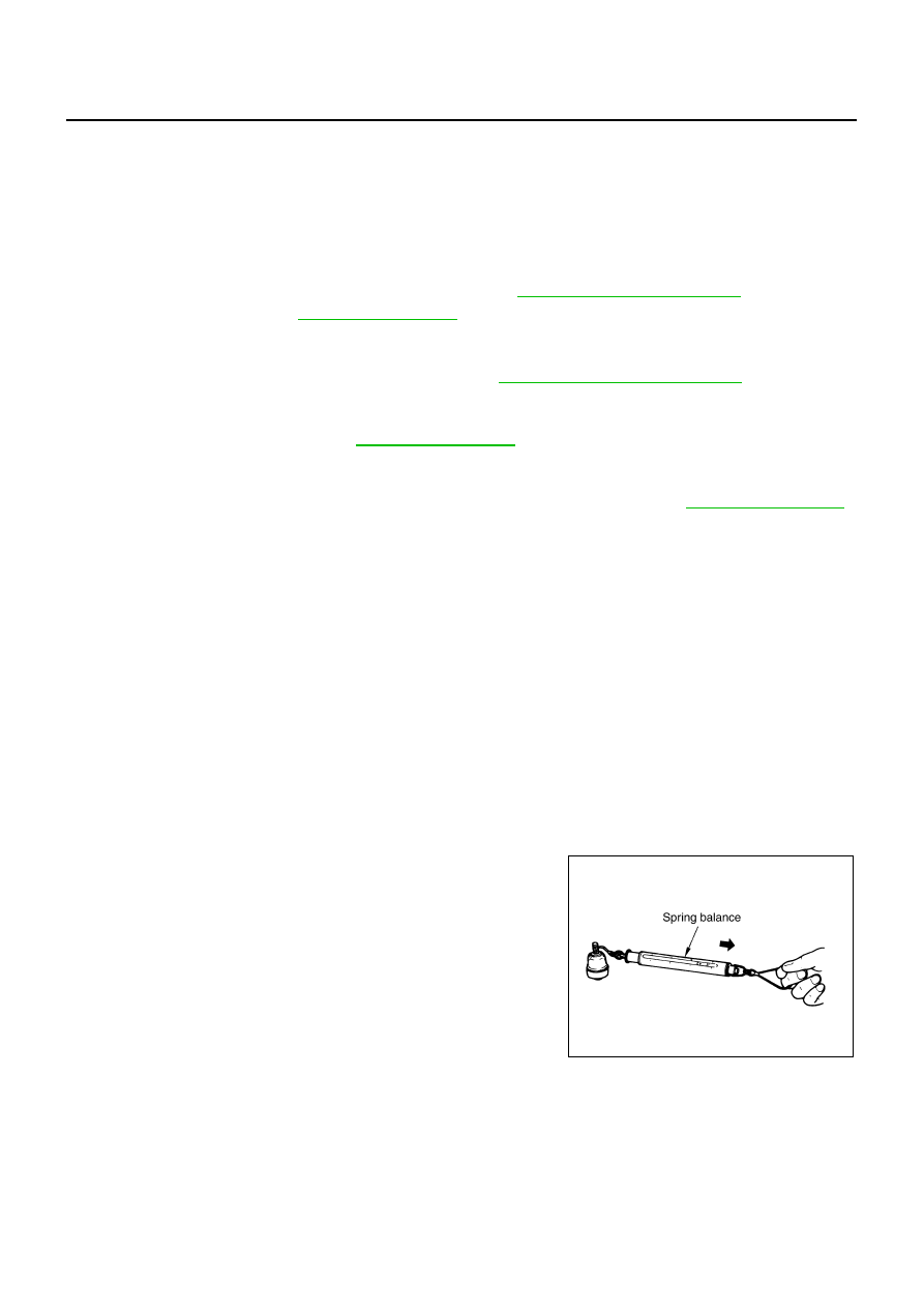
Hook a spring balance at cotter pin mounting hole. Confirm
spring balance measurement value is within specifications when
ball stud begins moving.
●
If it is outside the specified range, replace transverse link
assembly.
Swing torque
: 0.5 - 3.6 N·m (0.06 - 0.36 kg-m, 5 - 31 in-lb)
Spring balance measurement
: 7.8 - 56.3 N (0.8 - 5.7 kg, 1.8 - 12.5 lb)
SEIA0523E
TRANSVERSE LINK
FSU-15
[2WD]
C
D
F
G
H
I
J
K
L
M
A
B
FSU
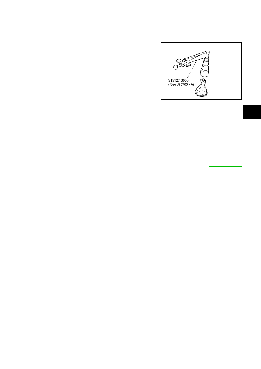
Rotating Torque Inspection
●
Attach mounting nut to ball stud. Make sure that rotating torque
is within specifications with a preload gauge [SST].
●
If it is outside the specified range, replace transverse link
assembly.
Axial End Play Inspection
●
Move tip of ball stud in axial direction to check for looseness.
●
If it is outside the specified range, replace transverse link assembly.
INSTALLATION
●
Installation is the reverse order of removal. For tightening torque, refer to
●
Perform final tightening of bolts and nuts at the front suspension member installation position and the
shock absorber lower side (rubber bushing) under unladen conditions with tires on level ground. Check
wheel alignment. Refer to
FSU-6, "Wheel Alignment Inspection"
●
Adjust neutral position of steering angle sensor after checking wheel alignment. Refer to
ment of Steering Angle Sensor Neutral Position"
Rotating torque
: 0.5 - 3.9 N·m (0.06 - 0.39 kg-m, 5 - 34 in-lb)
SDIA1150E
Axial end play
: 0 mm (0 in)
FSU-16
[2WD]
UPPER LINK
UPPER LINK
PFP:54524
Removal and Installation
NES000IH
REMOVAL
1.
Remove tires from vehicle with a power tool.
2.
Remove shock absorber. Refer to
FSU-11, "COIL SPRING AND SHOCK ABSORBER"
3.
Remove mounting nut and bolt with a power tool, and then remove upper link from steering knuckle.
4.
Remove mounting nuts and bolts, and then remove upper link and stopper rubber from vehicle.
INSPECTION AFTER REMOVAL
Visual Inspection
Check the following:
●
Upper link and bushing for deformation, cracks or damage. Replace it if a malfunction is detected.
●
Ball joint boot for cracks or other damage, and also for grease leakage. Replace it if a malfunction is
detected.
Ball Joint Inspection
Manually move ball stud to confirm it moves smoothly with no binding.
Swing Torque Inspection
NOTE:
Before measurement, move ball stud at least ten times by hand to check for smooth movement.
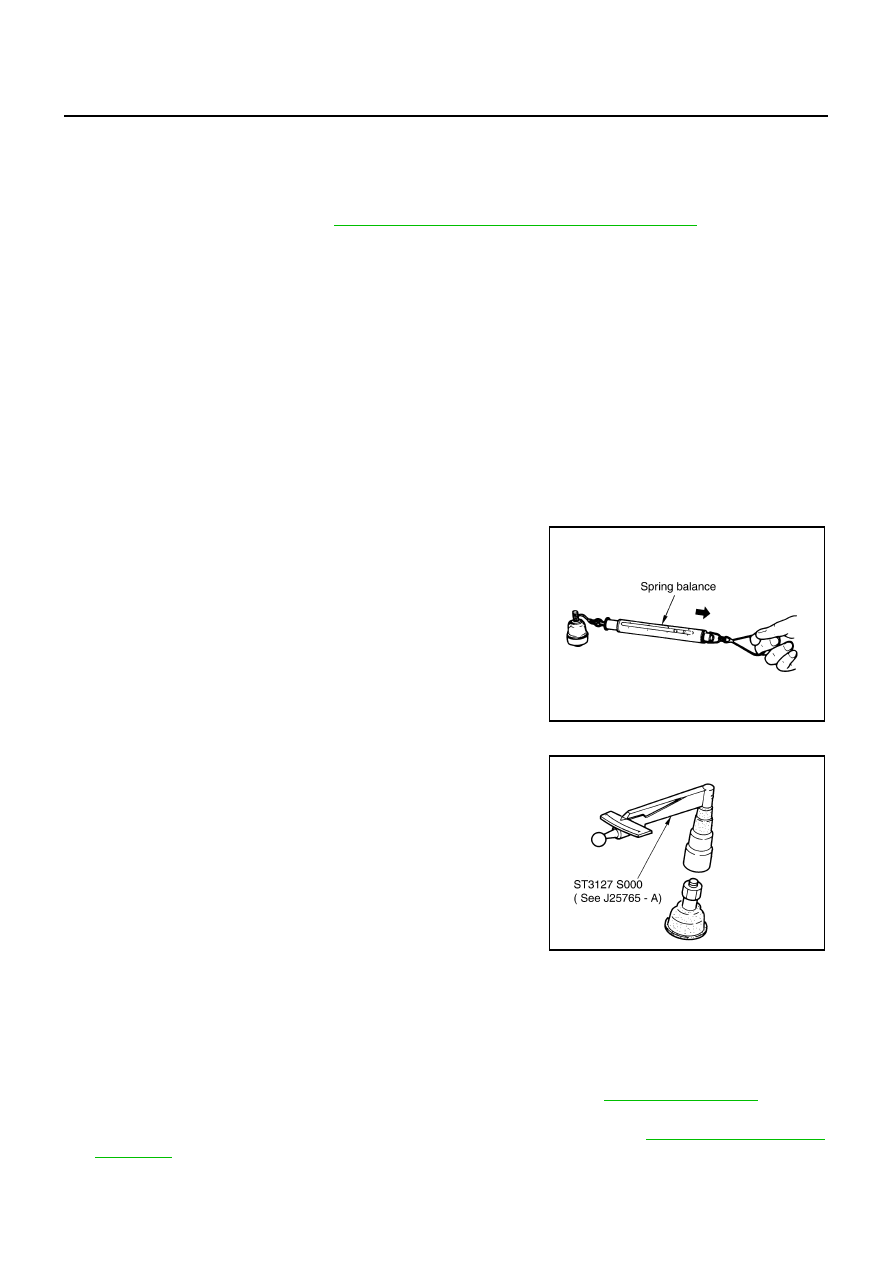
●
Hook a spring balance at cutout on ball stud. Confirm spring bal-
ance measurement value is within specifications when ball stud
begins moving.
●
If it is outside the specified range, replace upper link assembly.
Rotating Torque Inspection
●
Attach mounting nut to ball stud. Make sure that rotating torque
is within specifications with a preload gauge [SST].
●
If it is outside the specified range, replace upper link assembly.
Axial End Play Inspection
●
Move tip of ball stud in axial direction to check for looseness.
●
If it is outside the specified range, replace upper link assembly.
INSTALLATION
●
Installation is the reverse order of removal. For tightening torque, refer to
●
Perform final tightening of bolts and nuts at the vehicle installation position (rubber bushing) under
unladen conditions with tires on level ground. Check wheel alignment. Refer to
Swing torque
: 0 - 2.0 N·m (0 - 0.2 kg-m, 0 - 17 in-lb)
Spring balance measurement
: 0 - 61.5 N (0 - 6.2 kg, 0 - 13.6 lb)
SEIA0523E
Rotating torque
: 0 - 2.0 N·m (0 - 0.2 kg-m, 0 - 17 in-lb)
SDIA1150E
Axial end play
: 0 mm (0 in)
Нет комментариевНе стесняйтесь поделиться с нами вашим ценным мнением.
Текст