Infiniti M35/M45 Y50. Manual — part 134
TROUBLE DIAGNOSIS
ATC-87
C
D
E
F
G
H
I
K
L
M
A
B
ATC
COMPONENT DESCRIPTION
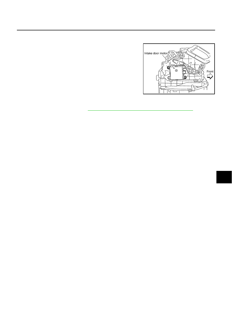
Intake Door Motor
The intake door motor is attached to the blower unit. It rotates so that
air is drawn from inlets set by the unified meter and A/C amp. Motor
rotation is conveyed to a lever which activates the intake door.
DIAGNOSIS PROCEDURE FOR INTAKE DOOR MOTOR
SYMPTOM: Intake door motor does not operate normally.
Perform diagnosis procedure. Refer to
ATC-71, "DIAGNOSIS PROCEDURE FOR LAN CIRCUIT"
.
RJIA4068E
ATC-88
TROUBLE DIAGNOSIS
Blower Motor Circuit
NJS000GT
SYMPTOM: Blower motor operation is malfunctioning.
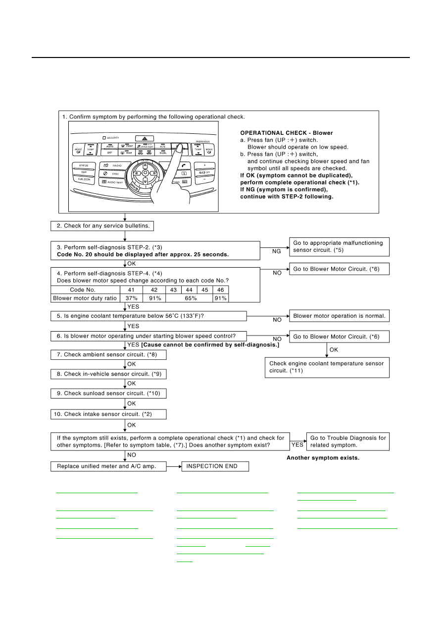
INSPECTION FLOW
*1
*2
ATC-121, "Intake Sensor Circuit"
*3
ATC-57, "FUNCTION CONFIRMA-
TION PROCEDURE"
, see No. 2.
*4
ATC-57, "FUNCTION CONFIRMA-
TION PROCEDURE"
, see No. 6.
*5
ATC-57, "FUNCTION CONFIRMA-
TION PROCEDURE"
, see No. 13.
*6
ATC-90, "DIAGNOSIS PROCE-
DURE FOR BLOWER MOTOR"
*7
*8
ATC-112, "Ambient Sensor Circuit"
*9
ATC-115, "In-vehicle Sensor Circuit"
*10
ATC-118, "Sunload Sensor Circuit"
*11
EC-214, "DTC P0117, P0118 ECT
SENSOR"
(VQ35DE) or
"DTC P0117, P0118 ECT SEN-
SOR"
(VK45DE)
RJIA4069E
TROUBLE DIAGNOSIS
ATC-89
C
D
E
F
G
H
I
K
L
M
A
B
ATC
SYSTEM DESCRIPTION
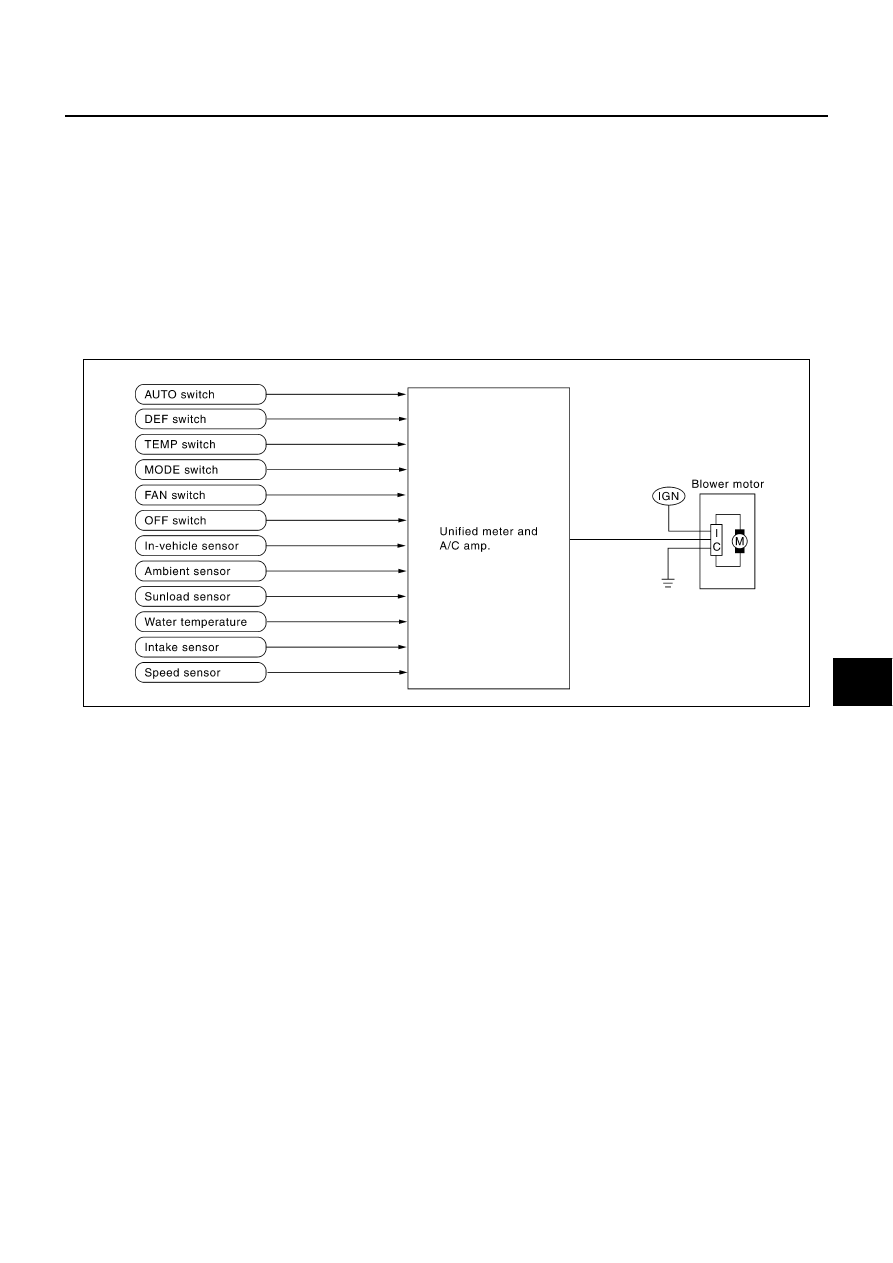
Component Parts
Fan speed control system components are:
●
Unified meter and A/C amp.
●
A/C LAN system (PBR built-in mode door motor, upper ventilator door motor, air mix door motor and
intake door motor)
●
In-vehicle sensor
●
Ambient sensor
●
Sunload sensor
●
Intake sensor
System Operation
Automatic Mode
In the automatic mode, the blower motor speed is calculated by the unified meter and A/C amp. based on the
input from the PBR, in-vehicle sensor, sunload sensor, intake sensor and ambient sensor.
When the air flow is increased, the duty ratio of the blower fan motor’s drive signal is changed at 8%/sec. to
prevent a sudden increase in air flow.
In addition to manual air flow control and the usual automatic air flow control, starting air flow control, low
water temperature starting control and high passenger compartment temperature starting control are avail-
able.
RJIA4070E
ATC-90
TROUBLE DIAGNOSIS
Starting Fan Speed Control
Start up from COLD SOAK Condition (Automatic mode)
In a cold start up condition where the engine coolant temperature is below 56
°
C (133
°
F), the blower will not
operate for a short period of time (up to 150 seconds). The exact start delay time varies depending on the
ambient and engine coolant temperature.
In the most extreme case (very low ambient) the blower starting delay will be 150 seconds as described
above. After this delay, the blower will operate at low speed until the engine coolant temperature rises above
56
°
C (133
°
F), and then the blower speed will increase to the objective speed.
Start up from usual or HOT SOAK Condition (Automatic mode)
The blower will begin operation momentarily after the AUTO switch is pressed. The blower speed will gradu-
ally rise to the objective speed over a time period of 3 seconds or less (actual time depends on the objective
blower speed).
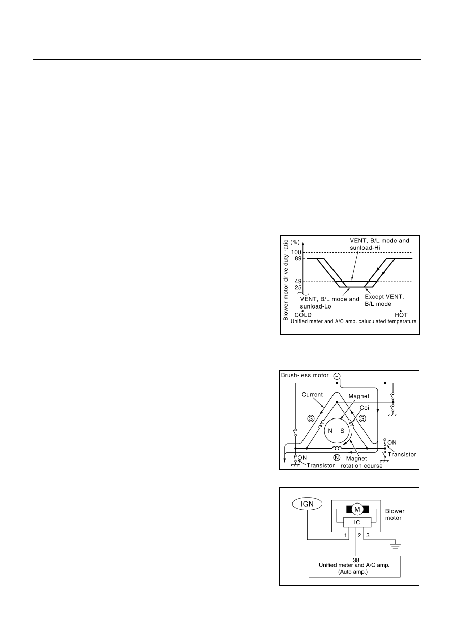
Blower Speed Compensation
Sunload
When the in-vehicle temperature and the set temperature are very close, the blower will be operating at low
speed. The low speed will vary depending on the sunload. During conditions of low or no sunload, the blower
speed is at duty ratio 25%. During high sunload conditions, the unified meter and A/C amp. raise the blower
speed (duty ratio 49%).
Fan Speed Control Specification
COMPONENT DESCRIPTION
Brush-less Motor
The blower motor utilizes a brush-less motor with a rotating magnet.
Quietness is improved over previous motors where the brush was
the point of contact and the coil rotated.
DIAGNOSIS PROCEDURE FOR BLOWER MOTOR
SYMPTOM: Blower motor operation is malfunctioning.
SJIA0942E
ZHA152H
RJIA4071E
Нет комментариевНе стесняйтесь поделиться с нами вашим ценным мнением.
Текст