Infiniti M35/M45 Y50. Manual — part 135
TROUBLE DIAGNOSIS
ATC-91
C
D
E
F
G
H
I
K
L
M
A
B
ATC
1.
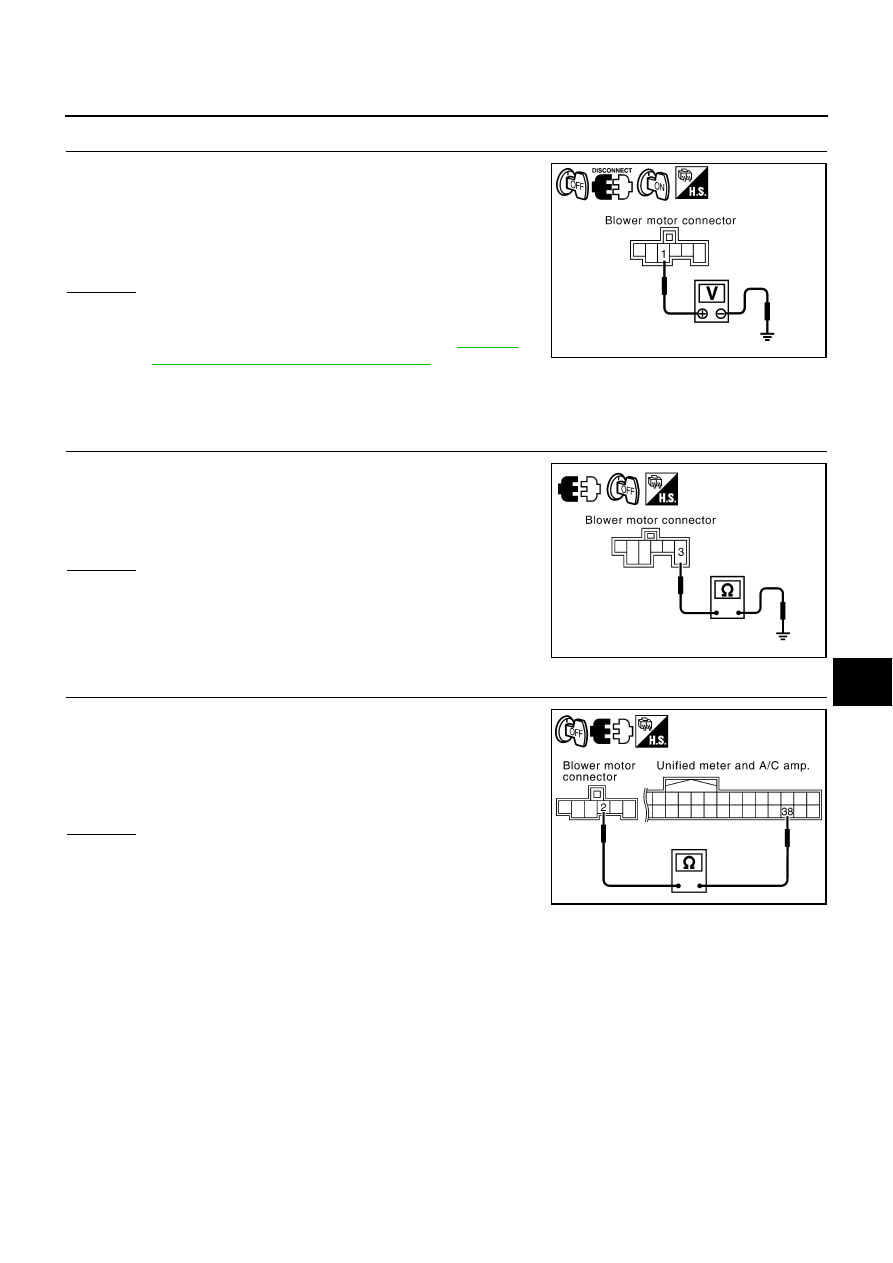
CHECK POWER SUPPLY FOR BLOWER MOTOR
1.
Disconnect blower motor connector.
2.
Turn ignition switch ON.
3.
Check voltage between blower motor harness connector M91
terminal 1 and ground.
OK or NG
OK
>> GO TO 2.
NG
>> Check power supply circuit and 15A fuses [Nos. 10 and
11, located in the fuse block (J/B)]. Refer to
"FUSE BLOCK - JUNCTION BOX (J/B)"
●
If fuses are OK, check harness for open circuit. Repair or replace if necessary.
●
If fuses are NG, check harness for short circuit and replace fuse.
2.
CHECK BLOWER MOTOR GROUND CIRCUIT
1.
Turn ignition switch OFF.
2.
Check continuity between blower motor harness connector M91
terminal 3 and ground.
OK or NG
OK
>> GO TO 3.
NG
>> Repair harness or connector.
3.
CHECK CIRCUIT CONTINUITY BETWEEN BLOWER MOTOR AND UNIFIED METER AND A/C AMP.
1.
Disconnect unified meter and A/C amp. connector.
2.
Check continuity between blower motor harness connector M91
terminal 2 and unified meter and A/C amp. harness connector
M64 terminal 38.
OK or NG
OK
>> GO TO 4.
NG
>> Repair harness or connector.
1 – Ground
: Battery voltage
RJIA1997E
3 – Ground
: Continuity should exist.
RJIA4072E
2 – 38
: Continuity should exist.
RJIA4073E
ATC-92
TROUBLE DIAGNOSIS
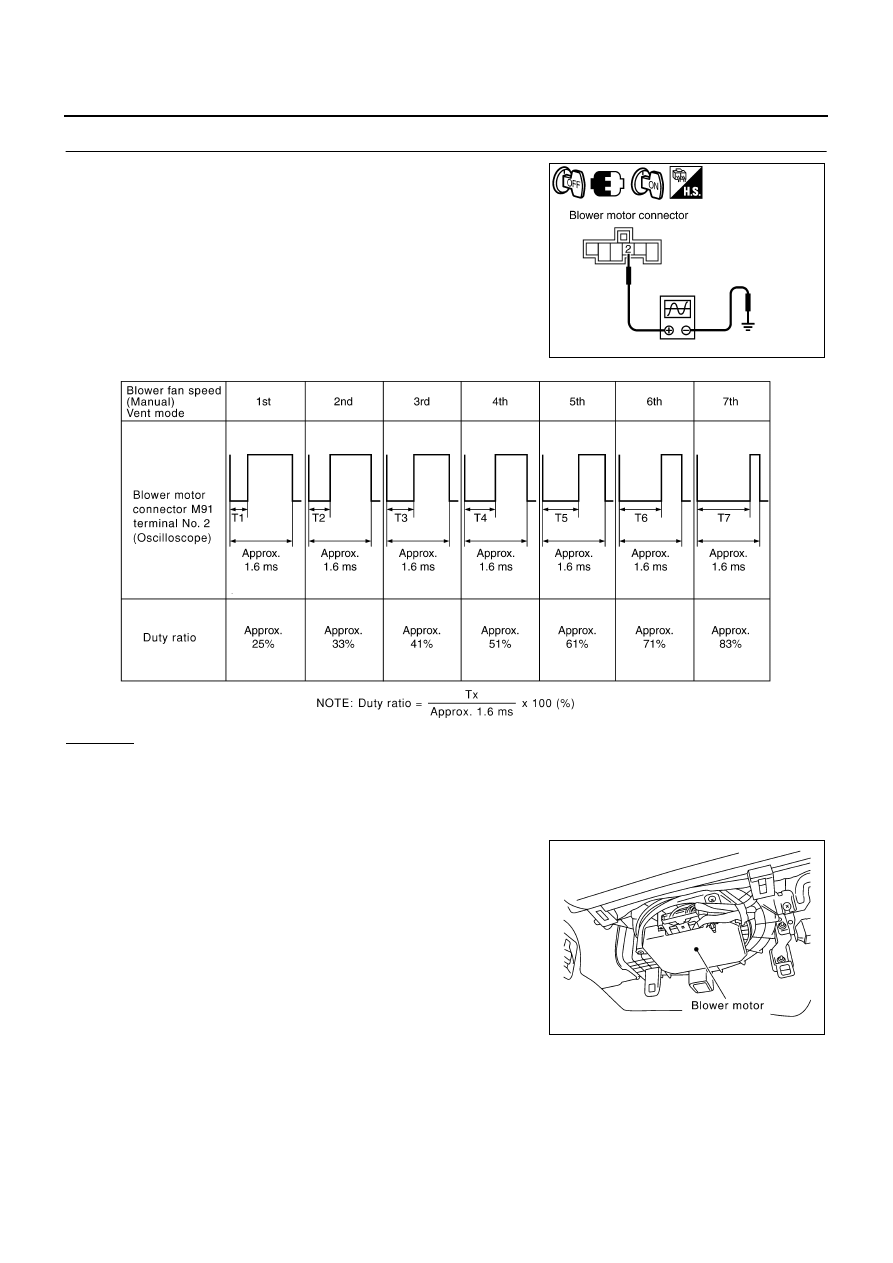
4.
CHECK UNIFIED METER AND A/C AMP. OUTPUT SIGNAL
1.
Reconnect blower motor connector and unified meter and A/C
amp. connector.
2.
Turn ignition switch ON.
3.
Set MODE switch to VENT position.
4.
Change the fan speed from Lo to Hi, and check the duty ratios
between blower motor harness connector M91 terminal 2 and
ground by using an oscilloscope. Normal terminal 2 drive signal
duty ratios are shown in the table below.
OK or NG
OK
>> Replace blower motor after confirming the fan air flow does not change.
NG
>> Replace unified meter and A/C amp.
COMPONENT INSPECTION
Blower Motor
Confirm smooth rotation of the blower motor.
●
Ensure that there are no foreign particles inside the blower unit.
RJIA4074E
RJIA4075E
RJIA4076E
TROUBLE DIAGNOSIS
ATC-93
C
D
E
F
G
H
I
K
L
M
A
B
ATC
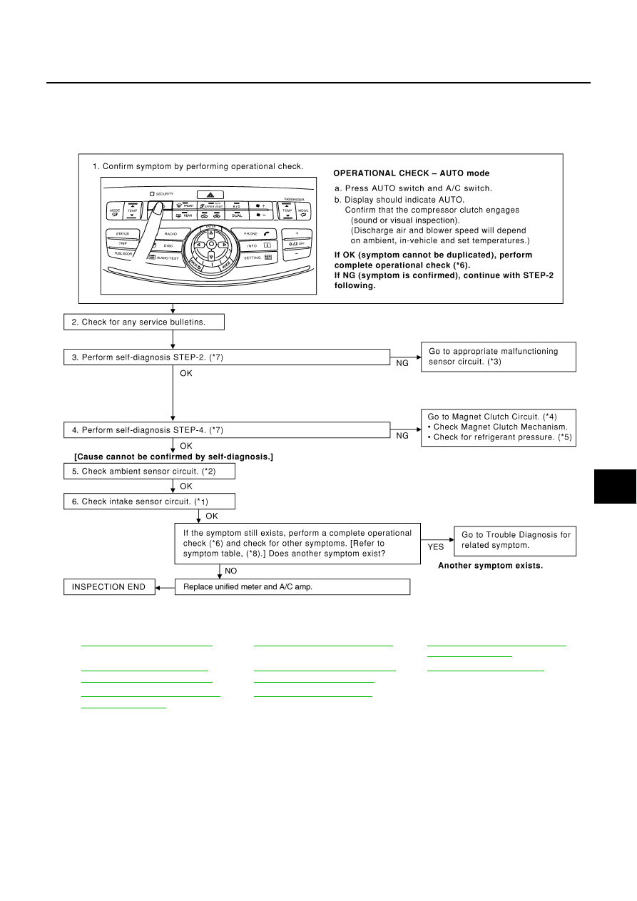
Magnet Clutch Circuit
NJS000GU
SYMPTOM: Magnet clutch does not engage.
INSPECTION FLOW
*1
ATC-121, "Intake Sensor Circuit"
*2
ATC-112, "Ambient Sensor Circuit"
*3
ATC-57, "FUNCTION CONFIRMA-
TION PROCEDURE"
, see No. 13.
*4
ATC-94, "DIAGNOSIS PROCE-
DURE FOR MAGNET CLUTCH"
*5
ATC-104, "TROUBLE DIAGNOSIS
FOR UNUSUAL PRESSURE"
*6
*7
ATC-57, "FUNCTION CONFIRMA-
TION PROCEDURE"
, see No. 2 to 6.
*8
RJIA4077E
ATC-94
TROUBLE DIAGNOSIS
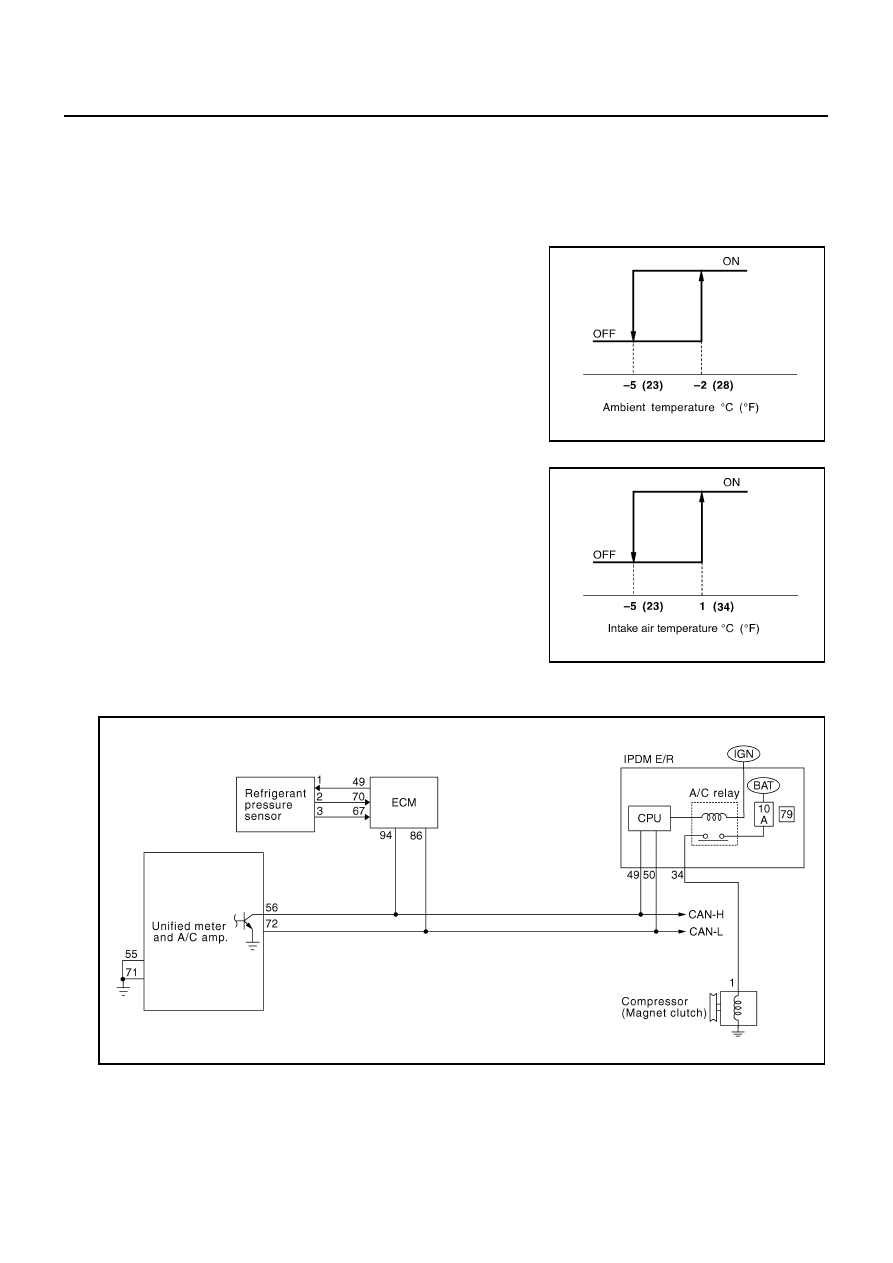
SYSTEM DESCRIPTION
Unified meter and A/C amp. controls compressor operation by ambient temperature, intake air temperature
and signal from ECM.
Low Temperature Protection Control
Unified meter and A/C amp. will turn compressor ON or OFF as determined by a signal detected by ambient
sensor and intake sensor.
When ambient temperature is higher than
−
2
°
C (28
°
F), the compres-
sor turns ON. The compressor turns OFF when ambient temperature
is lower than
−
5
°
C (23
°
F).
When intake air temperature is higher than 1
°
C (34
°
F), the compres-
sor turns ON. The compressor turns OFF when intake air tempera-
ture is lower than
−
5
°
C (23
°
F).
DIAGNOSIS PROCEDURE FOR MAGNET CLUTCH
SYMPTOM: Magnet clutch does not engage when A/C switch is ON.
RHA094GB
SJIA0267E
RJIA4078E
Нет комментариевНе стесняйтесь поделиться с нами вашим ценным мнением.
Текст