Infiniti M35/M45 Y50. Manual — part 1048

CHARGING SYSTEM
SC-27
C
D
E
F
G
H
I
J
L
M
A
B
SC
2.
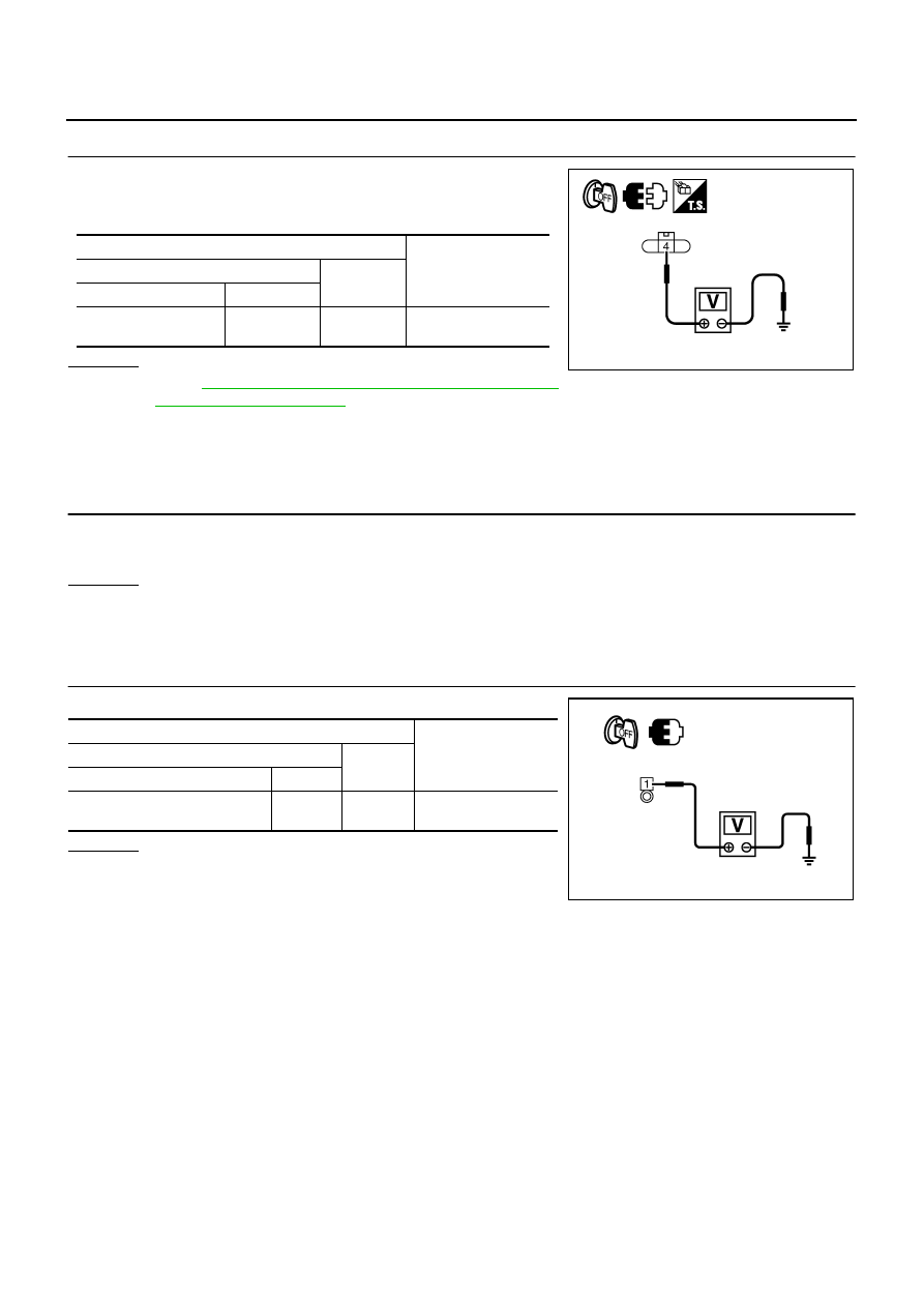
CHECK “L” TERMINAL CIRCUIT (OPEN)
1.
Disconnect alternator connector.
2.
Apply ground to alternator harness connector terminal.
3.
Check condition the charge warning lamp with the ignition
switch in the ON position.
OK or NG
OK
SC-25, "Trouble Diagnosis with Starting/Charging System Tester (Charging)"
NG
>> Check the following.
●
Harness for open between combination meter and alternator
●
Harness for open between combination meter and fuse
●
Charge warning lamp (Combination meter)
DIAGNOSTIC PROCEDURE 2
Check “L” Terminal Circuit (Short)
1.
CHECK “L” TERMINAL CIRCUIT (SHORT)
1.
Turn ignition switch OFF.
2.
Disconnect alternator connector.
3.
Turn ignition switch ON.
Charge warning lamp should illuminate?
YES
>> Check the following.
●
Harness for short between combination meter and alternator
●
Charge warning lamp (Combination meter)
NO
SC-25, "Trouble Diagnosis with Starting/Charging System Tester (Charging)"
DIAGNOSTIC PROCEDURE 3
Check “S” Terminal Circuit
1.
CHECK “S” TERMINAL CONNECTION
1.
Turn ignition switch OFF.
2.
Check if “S” terminal is clean and tight.
OK or NG
OK
>> GO TO 2.
NG
>> Repair “S” terminal connection. Confirm repair by performing complete Starting/Charging system
test. Refer to Technical Service Bulletin.
Alternator
connector
Terminal
Ground
Condition
Ignition switch
position
Charge warning
lamp
F20 (VQ35DE)
E209 (VK45DE)
3
ON
illuminate
PKIB8807E
SC-28
CHARGING SYSTEM
2.
CHECK “S” TERMINAL CIRCUIT
1.
Disconnect alternator connector.
2.
Check voltage between alternator harness connector and
ground.
OK or NG
OK
>> Go to
SC-25, "Trouble Diagnosis with Starting/Charging
NG
>> Check harness for open between alternator and fuse.
DIAGNOSTIC PROCEDURE 4
Check “B” Terminal Circuit
1.
CHECK “B” TERMINAL CONNECTION
1.
Turn ignition switch OFF.
2.
Check if “B” terminal is clean and tight.
OK or NG
OK
>> GO TO 2.
NG
>> Repair “B” terminal connection. Confirm repair by performing complete Starting/Charging system
test. Refer to Technical Service Bulletin.
2.
CHECK “B” TERMINAL CIRCUIT
Check voltage between alternator “B” terminal and ground.
OK or NG
OK
>> GO TO 3.
NG
>> Check harness for open between alternator and fusible
link.
Terminals
Voltage (Approx.)
(+)
(–)
Alternator connector
Terminal
F20 (VQ35DE)
E209 (VK45DE)
4
Ground
Battery voltage
PKIB8808E
Terminals
Voltage (Approx.)
(+)
(–)
Alternator “B” terminal
Terminal
E205 [VQ35DE (2WD)]
E202 [VQ35DE (AWD)/VK45DE]
1
Ground
Battery voltage
PKIB8809E

CHARGING SYSTEM
SC-29
C
D
E
F
G
H
I
J
L
M
A
B
SC
3.
CHECK “B” TERMINAL CONNECTION (VOLTAGE DROP TEST)
1.
Start engine, then engine running at idle and warm.
2.
Check voltage between battery positive terminal and alternator
“B” terminal.
OK or NG
OK
>> Go to
SC-25, "Trouble Diagnosis with Starting/Charging
.
NG
>> Check harness between battery and alternator for poor continuity.
Power Generation Voltage Variable Control System Operation Inspection
NKS003NQ
CAUTION:
●
For this model, the battery current sensor that is installed to the battery cable at the negative ter-
minal measures the charging/discharging current of the battery, and performs various controls. If
the electrical component or the ground wire is connected directly to the battery terminal, the cur-
rent other than that being measured with the battery current sensor is charging to or discharging
from the battery. This condition causes the malfunction of the control, and then the battery dis-
charge may occur. Never connect the electrical component or the ground wire directly to the bat-
tery terminal.
●
When performing this inspection, always use the charged battery that completed the battery
inspection. (When the charging rate of the battery is low, the response speed of the voltage
change will become slow. This is a cause of an incorrect inspection.)
INSPECTION PROCEDURE
1.
CHECK ECM (CONSULT-II)
Perform ECM self-diagnosis with CONSULT-II. Refer to the following.
●
VQ35DE:
EC-123, "CONSULT-II Function (ENGINE)"
●
VK45DE:
EC-826, "CONSULT-II Function (ENGINE)"
Self-diagnostic results content
No malfunction detected>> GO TO 2.
Malfunction detected>> Check applicable parts, and repair or replace corresponding parts.
Terminals
Voltage
(Approx.)
(+)
(–)
Alternator “B” terminal
Terminal
Battery positive
terminal
E205 [VQ35DE (2WD)]
E202 [VQ35DE (AWD)/VK45DE]
1
Less than 0.2 V
PKIB8810E
SC-30
CHARGING SYSTEM
2.
CHECK OPERATION OF POWER GENERATION VOLTAGE VARIABLE CONTROL SYSTEM
1.
Connect CONSULT-II and start the engine.
2.
The selector lever is in “P” or “N” position and all of the electric
loads and A/C, etc. are turned OFF.
3.
Select “ALTERNATOR DUTY” at “ACTIVE TEST” of “ENGINE”,
and then check the value of “BATTERY VOLT” monitor when
DUTY value of “ALTERNATOR DUTY” is set to 40.0 %.
4.
Check the value of “BATTERY VOLT” monitor when DUTY value
of “ALTERNATOR DUTY” is set to 80.0%.
OK or NG
OK
>> INSPECTION END
NG
>> GO TO 3. (The charging condition of the battery should
be normal.)
3.
CHECK IPDM E/R (CONSULT-II)
Perform IPDM E/R self-diagnosis with CONSULT-II. Refer to
PG-20, "CONSULT-II Function (IPDM E/R)"
Self-diagnostic results content
No malfunction detected>> GO TO 4.
Malfunction detected>> Check applicable parts, and repair or replace corresponding parts.
4.
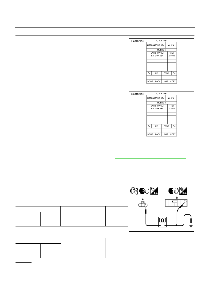
CHECK HARNESS BETWEEN ALTERNATOR AND IPDM E/R
1.
Turn ignition switch OFF.
2.
Disconnect alternator connector and IPDM E/R connector.
3.
Check continuity between alternator harness connector (A) and
IPDM E/R harness connector (B).
4.
Check continuity between alternator harness connector (A) and
ground.
OK or NG
OK
>> Replace IPDM E/R.
NG
>> Repair harness or connector between IPDM E/R and alternator.
“BATTERY VOLT”
2 seconds after setting the
DUTY value of “ALTERNA-
TOR DUTY” to 40.0 %
: 12 - 13.6 V
PKIB4503E
“BATTERY VOLT”
20 seconds after setting
the DUTY value of “ALTER-
NATOR DUTY” to 80.0 %
: +0.5 V or more against
the value of “BATTERY
VOLT” monitor when
DUTY value is 40.0 %
PKIB4504E
A
B
Continuity
Connector
Terminal
Connector
Terminal
F20 (VQ35DE)
E209 (VK45DE)
5
E8
33
Yes
A
Ground
Condition
Connector
Terminal
F20 (VQ35DE)
E209 (VK45DE)
5
No
PKIB8811E
Нет комментариевНе стесняйтесь поделиться с нами вашим ценным мнением.
Текст