Infiniti M35/M45 Y50. Manual — part 334
TROUBLE DIAGNOSIS FOR SYSTEM
BRC-37
[VDC/TCS/ABS]
C
D
E
G
H
I
J
K
L
M
A
B
BRC
ABS Actuator and Electric Unit (Control Unit) Power Supply and Ground Circuit
NFS000QO
INSPECTION PROCEDURE
1.
CHECK SELF-DIAGNOSIS RESULTS
Check self-diagnosis results.
Is above displayed on the self-diagnosis display?
YES
>> GO TO 2.
NO
>> INSPECTION END
2.
CHECK CONNECTOR
1.
Turn ignition switch OFF and disconnect ABS actuator and electric unit (control unit) connector E30,
check terminal for deformation, disconnection, looseness, and so on. If any malfunction is found, repair or
replace terminal.
2.
Reconnect connector and perform self-diagnosis.
OK or NG
OK
>> INSPECTION END
NG
>> GO TO 3.
3.
CHECK ABS ACTUATOR AND ELECTRIC UNIT (CONTROL UNIT) POWER SUPPLY CIRCUIT AND
GROUND CIRCUIT
1.
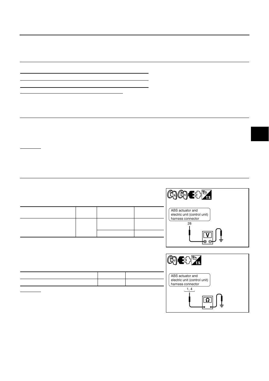
Turn ignition switch OFF and disconnect ABS actuator and electric unit (control unit) connector E30.
2.
Turn ignition switch ON or OFF and check voltage between ABS
actuator and electric unit (control unit) harness connector E30
terminal 28 and ground.
3.
Turn ignition switch OFF and check continuity between ABS
actuator and electric unit (control unit) harness connector E30
terminals 1, 4 and ground.
OK or NG
OK
>>
●
Check battery for terminal looseness, low voltage,
etc. If any malfunction is found, repair malfunctioning
parts.
●
Perform the self-diagnosis, and make sure that the
result shows “NO DTC IS DETECTED”.
NG
>>
●
Repair or replace malfunctioning components.
●
Perform the self-diagnosis, and make sure that the result shows “NO DTC IS DETECTED”.
Self-diagnosis results
BATTERY VOLTAGE [ABNORMAL]
ABS actuator and electric unit
(control unit)
Ground
Condition
Voltage
28
—
Ignition switch ON
Battery voltage
(Approx. 12 V)
Ignition switch OFF
Approx. 0 V
SFIA3032E
ABS actuator and electric unit (control unit)
Ground
Continuity
1, 4
—
Yes
SFIA3033E
BRC-38
[VDC/TCS/ABS]
TROUBLE DIAGNOSIS FOR SYSTEM
ABS Motor and Motor Relay Circuit
NFS000QP
INSPECTION PROCEDURE
1.
CHECK SELF-DIAGNOSIS RESULTS
Check self-diagnosis results.
Is above displayed on the self-diagnosis display?
YES
>> GO TO 2.
NO
>> INSPECTION END
2.
CHECK CONNECTOR
1.
Turn ignition switch OFF and disconnect ABS actuator and electric unit (control unit) connector E30,
check terminal for deformation, disconnection, looseness, and so on. If any malfunction is found, repair or
replace terminal.
2.
Reconnect connector and perform self-diagnosis.
OK or NG
OK
>> INSPECTION END
NG
>> GO TO 3.
3.
CHECK ABS MOTOR AND MOTOR RELAY POWER SUPPLY CIRCUIT
1.
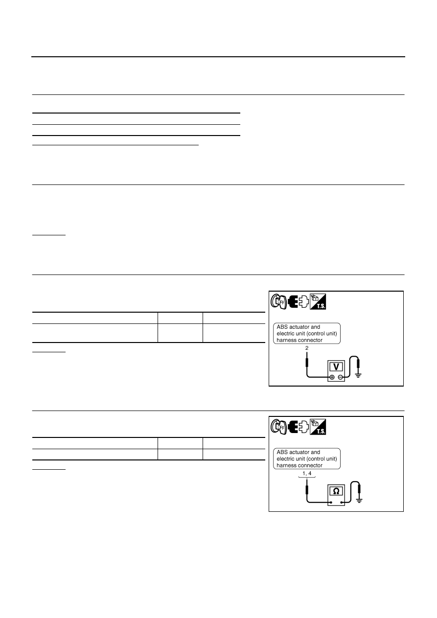
Turn ignition switch OFF and disconnect ABS actuator and electric unit (control unit) connector E30.
2.
Check voltage between the ABS actuator and electric unit (con-
trol unit) harness connector E30 terminal 2 and ground.
OK or NG
OK
>> GO TO 4.
NG
>>
●
Repair or replace malfunctioning components.
●
Perform the self-diagnosis, and make sure that the
result shows “NO DTC IS DETECTED”.
4.
CHECK ABS ACTUATOR AND ELECTRIC UNIT (CONTROL UNIT) GROUND CIRCUIT
Check continuity between ABS actuator and electric unit (control
unit) harness connector E30 terminals 1, 4 and ground.
OK or NG
OK
>>
●
Replace ABS actuator and electric unit (control unit).
●
Perform the self-diagnosis, and make sure that the
result shows “NO DTC IS DETECTED”.
NG
>>
●
Repair or replace malfunctioning components.
●
Perform the self-diagnosis, and make sure that the
result shows “NO DTC IS DETECTED”.
Self-diagnosis results
PUMP MOTOR
ABS actuator and electric unit (control unit)
Ground
Voltage
2
—
Battery voltage
(Approx. 12 V)
SFIA3034E
ABS actuator and electric unit (control unit)
Ground
Continuity
1, 4
—
Yes
SFIA3033E
TROUBLE DIAGNOSIS FOR SYSTEM
BRC-39
[VDC/TCS/ABS]
C
D
E
G
H
I
J
K
L
M
A
B
BRC
Solenoid, VDC Change-Over Valve and Actuator Relay Circuit
NFS000QQ
INSPECTION PROCEDURE
1.
CHECK SELF-DIAGNOSIS RESULTS
Check self-diagnosis results.
Is above displayed on the self-diagnosis display?
YES
>> GO TO 2.
NO
>> INSPECTION END
2.
CHECK CONNECTOR
1.
Turn ignition switch OFF and disconnect ABS actuator and electric unit (control unit) connector E30,
check terminal for deformation, disconnection, looseness, and so on. If any malfunction is found, repair or
replace terminal.
2.
Reconnect connector and perform self-diagnosis.
OK or NG
OK
>> INSPECTION END
NG
>> GO TO 3.
3.
CHECK SOLENOID, VDC CHANGE-OVER VALVE AND ACTUATOR RELAY POWER SUPPLY CIR-
CUIT
1.
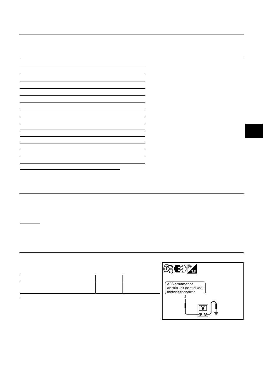
Turn ignition switch OFF and disconnect ABS actuator and electric unit (control unit) connector E30.
2.
Check voltage between ABS actuator and electric unit (control
unit) harness connector E30 terminal 3 and ground.
OK or NG
OK
>> GO TO 4.
NG
>>
●
Repair or replace malfunctioning components.
●
Perform the self-diagnosis, and make sure that the
result shows “NO DTC IS DETECTED”.
Self-diagnosis results
FR RH IN ABS SOL
FR RH OUT ABS SOL
FR LH IN ABS SOL
FR LH OUT ABS SOL
RR RH IN ABS SOL
RR RH OUT ABS SOL
RR LH IN ABS SOL
RR LH OUT ABS SOL
USV LINE [FL-RR]
USV LINE [FR-RL]
HSV LINE [FL-RR]
HSV LINE [FR-RL]
MAIN RELAY
ABS actuator and electric unit (control unit)
Ground
Voltage
3
—
Battery Voltage
(Approx. 12 V)
SFIA3035E
BRC-40
[VDC/TCS/ABS]
TROUBLE DIAGNOSIS FOR SYSTEM
4.
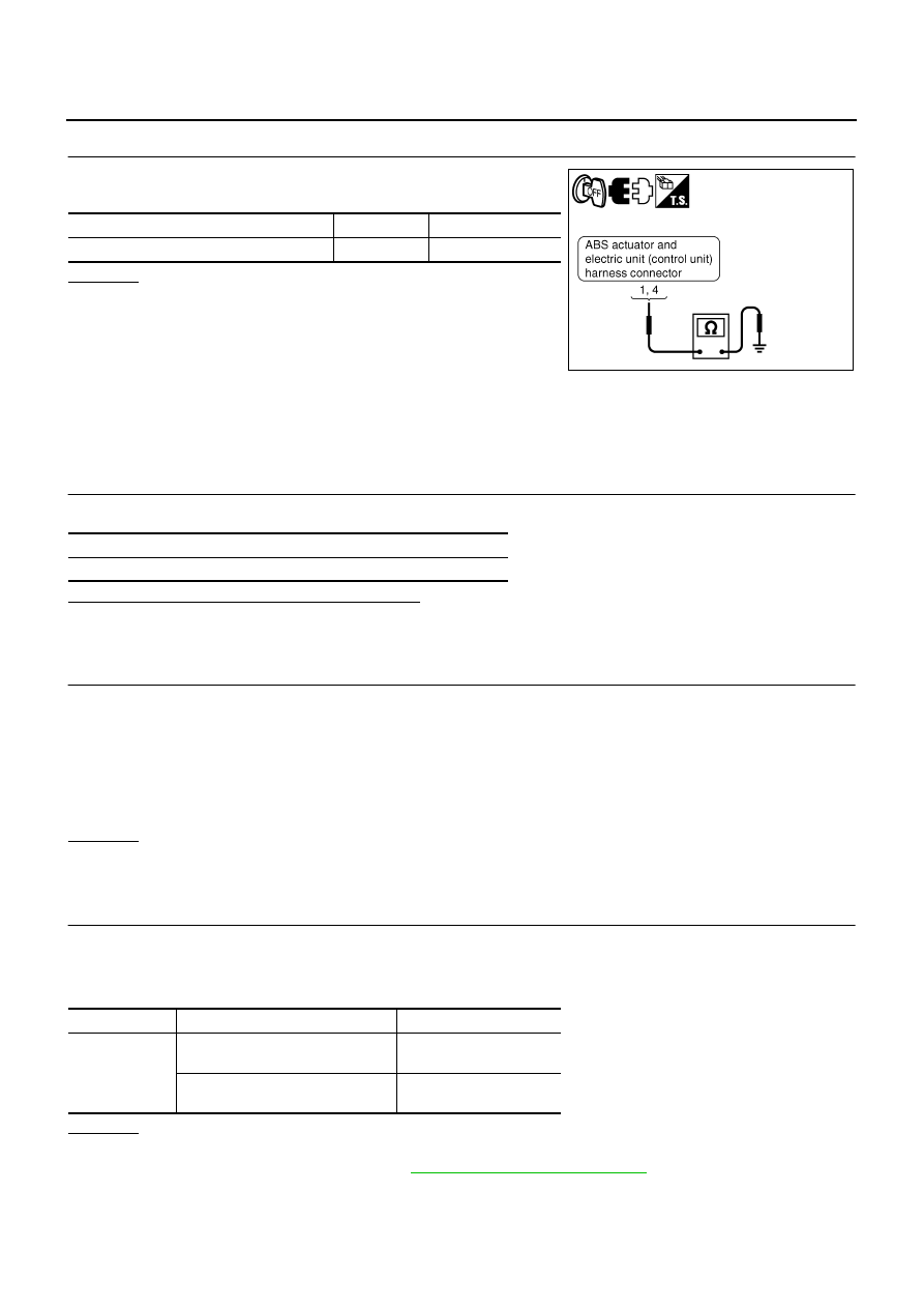
CHECK SOLENOID, VDC CHANGE-OVER VALVE, ACTUATOR RELAY GROUND CIRCUIT
Check continuity between ABS actuator and electric unit (control
unit) harness connector E30 terminals 1, 4 and ground.
OK or NG
OK
>>
●
Replace ABS actuator and electric unit (control unit).
●
Perform the self-diagnosis, and make sure that the
result shows “NO DTC IS DETECTED”.
NG
>>
●
Repair or replace malfunctioning components.
●
Perform the self-diagnosis, and make sure that the
result shows “NO DTC IS DETECTED”.
Pressure Sensor Circuit
NFS000QR
INSPECTION PROCEDURE
1.
CHECK SELF-DIAGNOSTIC RESULTS
Check self-diagnosis results.
Is above displayed on the self-diagnosis display?
YES
>> GO TO 2.
NO
>> INSPECTION END
2.
CHECK STOP LAMP SWITCH CONNECTOR
1.
Disconnect stop lamp switch connector and ABS actuator and electric unit (control unit) connector.
2.
Check terminals for deformation, disconnection, looseness, and so on. If any malfunction is found, repair
or replace terminal.
3.
Reconnect connectors securely.
4.
Start engine.
5.
Repeat pumping brake pedal carefully several times, then perform the self-diagnosis again.
OK or NG
OK
>> Connector terminal contact is loose, damaged, open or shorted.
NG
>> GO TO 3.
3.
CHECK STOP LAMP SWITCH
1.
Turn ignition switch OFF.
2.
Disconnect stop lamp switch harness connector E124.
3.
Operate stop lamp switch and check continuity between stop lamp switch harness connector terminals.
OK or NG
OK
>> GO TO 4.
NG
>> Replace stop lamp switch. Refer to
BR-7, "Removal and Installation"
ABS actuator and electric unit (control unit)
Ground
Continuity
1, 4
—
Yes
SFIA3033E
Self-diagnosis results
PRESS SEN CIRCUIT
Terminal
Condition
Continuity
3
−
4
Release stop lamp switch
(When brake pedal is depressed.)
Yes
Push stop lamp switch
(When brake pedal is released.)
No
Нет комментариевНе стесняйтесь поделиться с нами вашим ценным мнением.
Текст