Infiniti M35/M45 Y50. Manual — part 190
REMOVAL AND INSTALLATION
AV-137
[WITHOUT MOBILE ENTERTAINMENT SYSTEM]
C
D
E
F
G
H
I
J
L
M
A
B
AV
3.
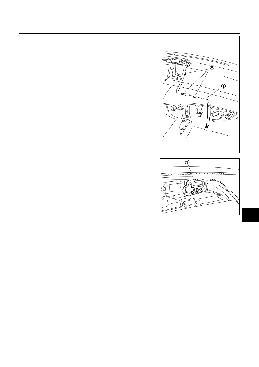
Remove clips (A) and remove antenna feeder (1) from instru-
ment panel and pad.
4.
Remove screw (A) and remove GPS antenna (1).
INSTALLATION
Installation is the reverse order of removal.
SKIB4365E
SKIB4366E
AV-138
[WITHOUT MOBILE ENTERTAINMENT SYSTEM]
REMOVAL AND INSTALLATION
Camera Control Unit
NKS004A4
REMOVAL
1.
Remove trunk side finisher (RH). Refer to
EI-56, "Removal and Installation for Trunk Room Trim"
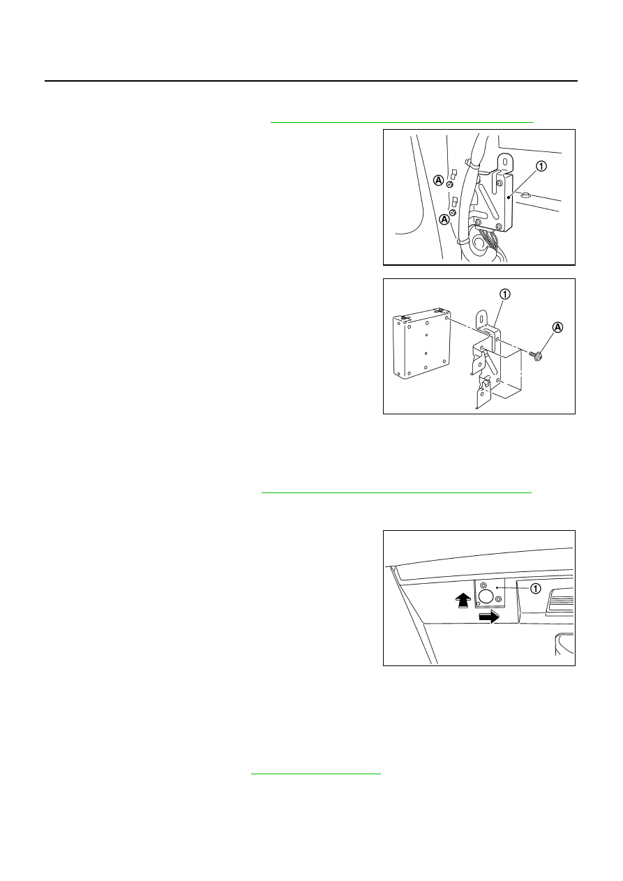
2.
Remove screws (A) and disconnect connector, and remove rear
view camera control unit (1).
3.
Remove screws (A) and remove bracket (1).
INSTALLATION
Installation is the reverse order of removal.
Rear View Camera
NKS004A5
REMOVAL
1.
Remove trunk lid finisher inner. Refer to
EI-56, "TRUNK ROOM TRIM & TRUNK LID FINISHER"
.
2.
Remove screws attaching camera and camera bracket.
3.
Remove connector and connector clip.
4.
Remove camera bracket (1) while pushing right direction of
vehicle.
INSTALLATION
1.
Install rear view camera and camera bracket while pressing to trunk room side.
2.
Install connector and connector clip.
3.
Install trunk lid finisher inner.
Steering Angle Sensor
NKS004A6
REMOVAL
1.
Remove combination switch. Refer to
.
SKIB4398E
SKIB4399E
SKIB5010E
REMOVAL AND INSTALLATION
AV-139
[WITHOUT MOBILE ENTERTAINMENT SYSTEM]
C
D
E
F
G
H
I
J
L
M
A
B
AV
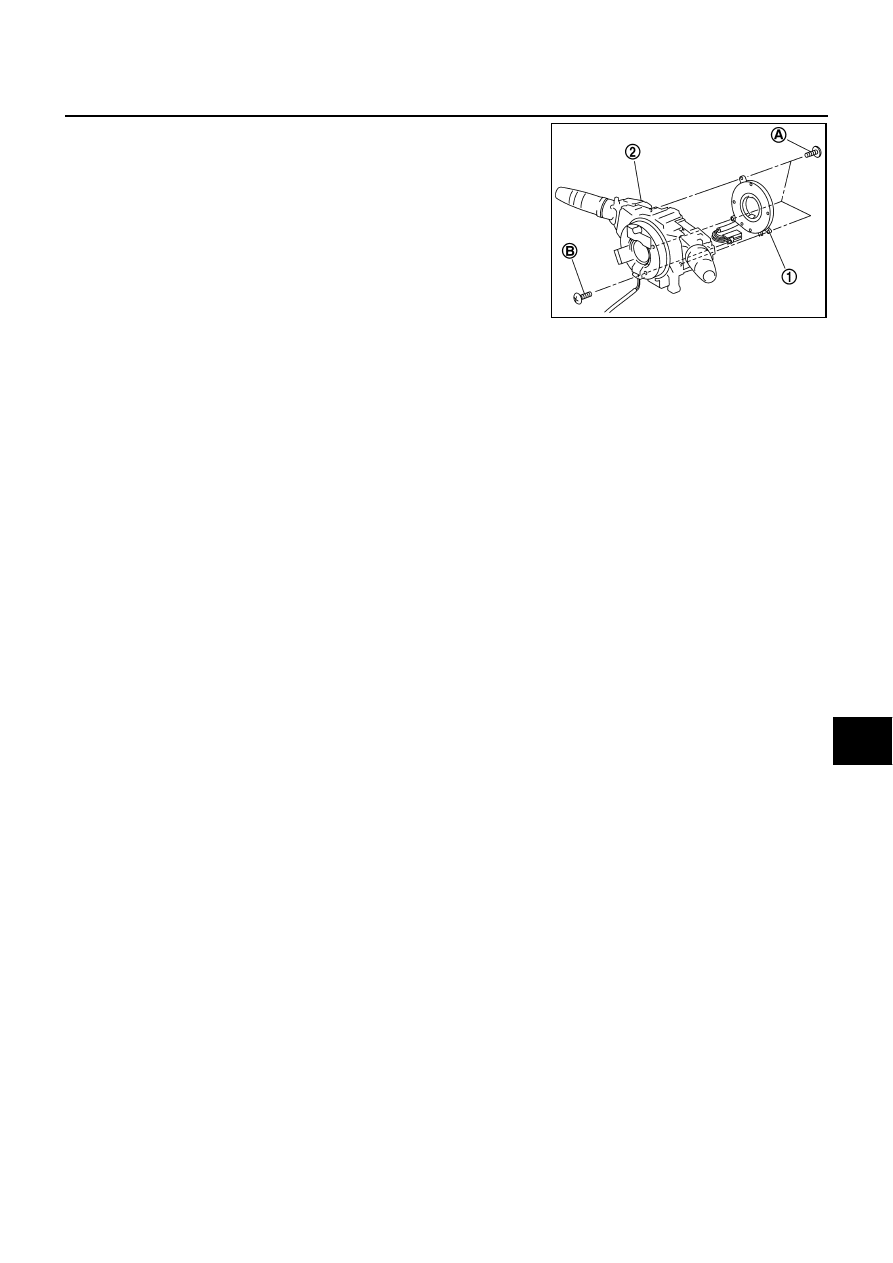
2.
Remove screws (A) and remove connector mount screw (B).
3.
Remove steering angle sensor (1) from combination switch (2).
INSTALLATION
Installation is the reverse order of removal.
CAUTION:
Insert the projection area, and install steering wheel angle sensor while fitting adjusting the triangle
marks (Larger mark should be upward.).
SKIB4352E
AV-140
[WITH MOBILE ENTERTAINMENT SYSTEM]
PRECAUTION
[WITH MOBILE ENTERTAINMENT SYSTEM]
PRECAUTION
PFP:00011
Precautions for Supplemental Restraint System (SRS) “AIR BAG” and “SEAT
BELT PRE-TENSIONER”
NKS004A7
The Supplemental Restraint System such as “AIR BAG” and “SEAT BELT PRE-TENSIONER”, used along
with a front seat belt, helps to reduce the risk or severity of injury to the driver and front passenger for certain
types of collision. This system includes seat belt switch inputs and dual stage front air bag modules. The SRS
system uses the seat belt switches to determine the front air bag deployment, and may only deploy one front
air bag, depending on the severity of a collision and whether the front occupants are belted or unbelted.
Information necessary to service the system safely is included in the SRS and SB section of this Service Man-
ual.
WARNING:
●
To avoid rendering the SRS inoperative, which could increase the risk of personal injury or death
in the event of a collision which would result in air bag inflation, all maintenance must be per-
formed by an authorized NISSAN/INFINITI dealer.
●
Improper maintenance, including incorrect removal and installation of the SRS, can lead to per-
sonal injury caused by unintentional activation of the system. For removal of Spiral Cable and Air
Bag Module, see the SRS section.
●
Do not use electrical test equipment on any circuit related to the SRS unless instructed to in this
Service Manual. SRS wiring harnesses can be identified by yellow and/or orange harnesses or
harness connectors.
Precautions for Trouble Diagnosis
NKS004A8
AV COMMUNICATION SYSTEM
●
Do not apply voltage of 7.0 V or higher to the measurement terminals.
●
Use the tester with its open terminal voltage being 7.0 V or less.
●
Be sure to turn ignition switch OFF and disconnect the battery cable from the negative terminal before
checking the circuit.
Precautions for Harness Repair
NKS004A9
AV COMMUNICATION SYSTEM
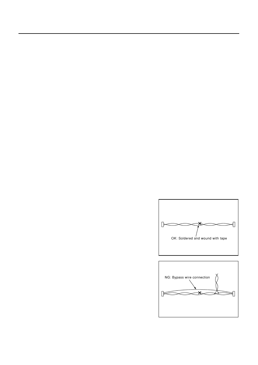
●
Solder the repaired parts, and wrap with tape. [Frays of twisted
line must be within 110 mm (4.33 in).]
●
Do not perform bypass wire connections for the repair parts.
(The spliced wire will become separated and the characteristics
of twisted line will be lost.)
PKIA0306E
PKIA0307E
Нет комментариевНе стесняйтесь поделиться с нами вашим ценным мнением.
Текст