Infiniti M35/M45 Y50. Manual — part 429
DTC P0075, P0081 IVT CONTROL SOLENOID VALVE
EC-189
[VQ35DE]
C
D
E
F
G
H
I
J
K
L
M
A
EC
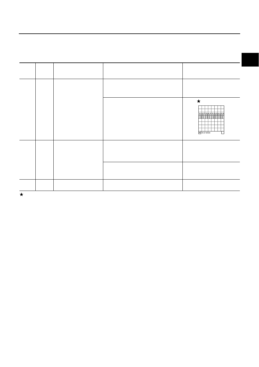
Specification data are reference values and are measured between each terminal and ground.
Pulse signal is measured by CONSULT-II.
CAUTION:
Do not use ECM ground terminals when measuring input/output voltage. Doing so may result in dam-
age to the ECM's transistor. Use a ground other than ECM terminals, such as the ground.
: Average voltage for pulse signal (Actual pulse signal can be confirmed by oscilloscope.)
TER-
MINAL
NO.
WIRE
COLOR
ITEM
CONDITION
DATA (DC Voltage)
10
W/G
Intake valve timing control
solenoid valve (bank 2)
[Engine is running]
●
Warm-up condition
●
Idle speed
BATTERY VOLTAGE
(11 - 14V)
[Engine is running]
●
Warm-up condition
●
When revving engine up to 2,000rpm
quickly
7 - 12V
111
SB
ECM relay
(Self shut-off)
[Engine is running]
[Ignition switch: OFF]
●
For a few seconds after turning ignition
switch OFF
0 - 1.5V
[Ignition switch: OFF]
●
More than a few seconds after turning igni-
tion switch OFF
BATTERY VOLTAGE
(11 - 14V)
119
120
R
R
Power supply for ECM
[Ignition switch: ON]
BATTERY VOLTAGE
(11 - 14V)
PBIB1790E
EC-190
[VQ35DE]
DTC P0075, P0081 IVT CONTROL SOLENOID VALVE
Diagnostic Procedure
NBS004UL
1.
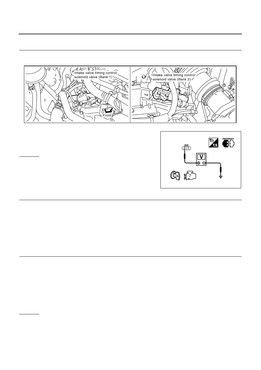
CHECK INTAKE VALVE TIMING CONTROL SOLENOID VALVE POWER SUPPLY CIRCUIT
1.
Turn ignition switch OFF.
2.
Disconnect intake valve timing control solenoid valve harness connector.
3.
Turn ignition switch ON.
4.
Check voltage between intake valve timing control solenoid
valve terminal 2 and ground with CONSULT-II or tester.
OK or NG
OK
>> GO TO 3.
NG
>> GO TO 2.
2.
DETECT MALFUNCTIONING PART
Check the following.
●
Harness connectors E12, F3
●
Harness connectors E18, F201 (bank 1)
●
Harness for open or short between intake valve timing control solenoid valve and IPDM E/R
>> Repair open circuit or short to ground or short to power in harness or connectors.
3.
CHECK INTAKE VALVE TIMING CONTROL SOLENOID VALVE OUTPUT SIGNAL CIRCUIT FOR
OPEN AND SHORT
1.
Turn ignition switch OFF.
2.
Disconnect ECM harness connector.
3.
Check harness continuity between the following;
ECM terminal 11 and intake valve timing control solenoid valve (bank 1) terminal 1 or
ECM terminal 10 and intake valve timing control solenoid valve (bank 2) terminal 1.
Refer to Wiring Diagram.
4.
Also check harness for short to ground and short to power.
OK or NG
OK
>> GO TO 5.
NG
>> GO TO 4.
Voltage: Battery voltage
PBIB1562E
PBIB0192E
Continuity should exist.
DTC P0075, P0081 IVT CONTROL SOLENOID VALVE
EC-191
[VQ35DE]
C
D
E
F
G
H
I
J
K
L
M
A
EC
4.
DETECT MALFUNCTIONING PART
Check the following.
●
Harness connectors F201, F18 (bank 1)
●
Harness for open or short between intake valve timing control solenoid valve and ECM
>> Repair open circuit or short to ground or short to power in harness or connectors.
5.
CHECK INTAKE VALVE TIMING CONTROL SOLENOID VALVE
Refer to
EC-192, "Component Inspection"
OK or NG
OK
>> GO TO 6.
NG
>> Replace malfunctioning intake valve timing control solenoid valve.
6.
CHECK INTERMITTENT INCIDENT
Refer to
EC-153, "TROUBLE DIAGNOSIS FOR INTERMITTENT INCIDENT"
>> INSPECTION END
EC-192
[VQ35DE]
DTC P0075, P0081 IVT CONTROL SOLENOID VALVE
Component Inspection
NBS004UM
INTAKE VALVE TIMING CONTROL SOLENOID VALVE
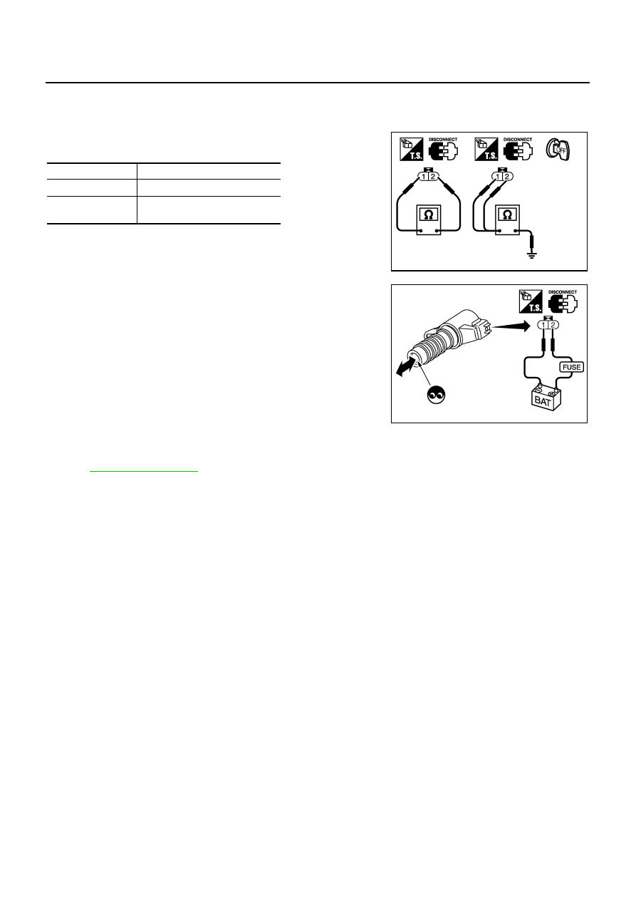
1.
Disconnect intake valve timing control solenoid valve harness connector.
2.
Check resistance between intake valve timing control solenoid
valve terminals as follows.
If NG, replace intake valve timing control solenoid valve.
If OK, go to next step.
3.
Remove intake valve timing control solenoid valve.
4.
Provide 12V DC between intake valve timing control solenoid
valve terminals and then interrupt it. Make sure that the plunger
moves as shown in the figure.
CAUTION:
Do not apply 12V DC continuously for 5 seconds or more.
Doing so may result in damage to the coil in intake valve
timing control solenoid valve.
If NG, replace intake valve timing control solenoid valve.
NOTE:
Always replace O-ring when intake valve timing control
solenoid valve is removed.
Removal and Installation
NBS004UN
INTAKE VALVE TIMING CONTROL SOLENOID VALVE
Refer to
.
Terminals
Resistance
1 and 2
7.0 - 7.5
Ω
[at 20
°
C (68
°
F)]
1 or 2 and ground
∞Ω
(Continuity should not exist)
PBIB0193E
PBIB2275E
Нет комментариевНе стесняйтесь поделиться с нами вашим ценным мнением.
Текст