Infiniti M35/M45 Y50. Manual — part 263
INTELLIGENT KEY SYSTEM
BL-121
C
D
E
F
G
H
J
K
L
M
A
B
BL
Check Key Slot Illumination
NIS001Y1
1.
CHECK KEY SLOT ILLUMINATION OUTPUT SIGNAL
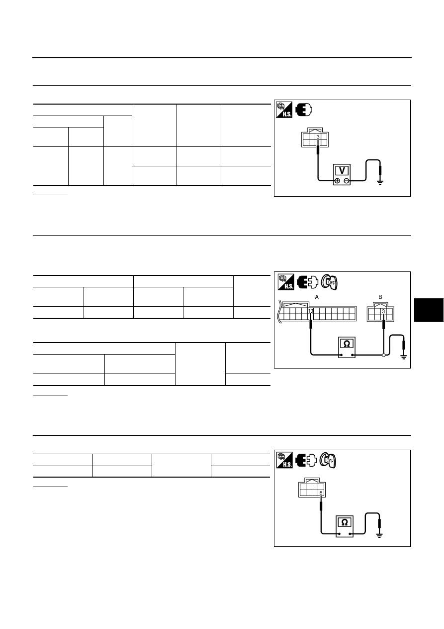
Check voltage between key slot connector and ground.
OK or NG
OK
>> Key slot illumination is OK.
NG
>> GO TO 2.
2.
CHECK HARNESS CONTINUITY
1.
Turn ignition switch OFF.
2.
Disconnect Intelligent Key unit and key slot connector.
3.
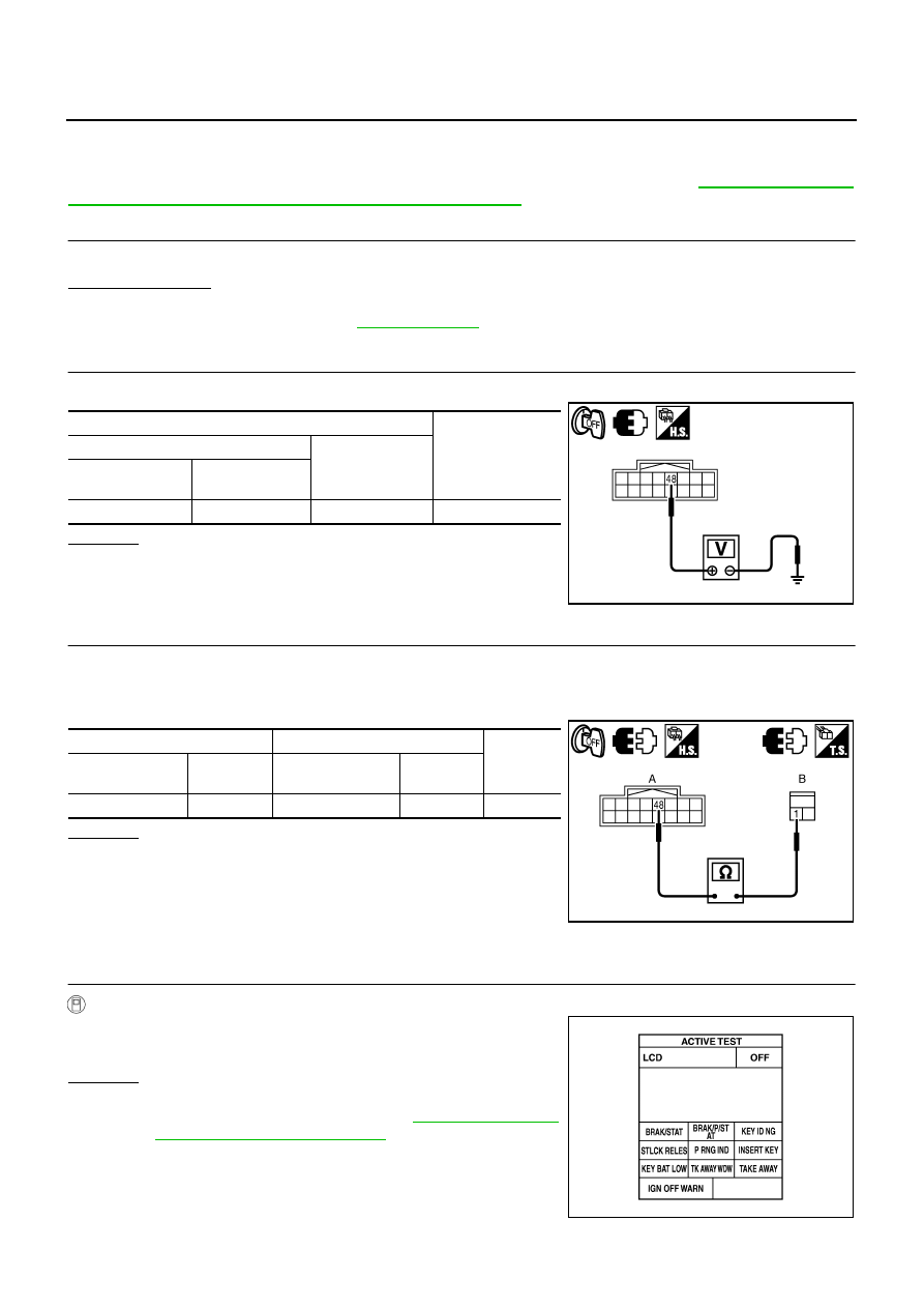
Check continuity between Intelligent Key unit connector and key slot connector.
4.
Check continuity between Intelligent Key unit connector and
ground.
OK or NG
OK
>> GO TO 3.
NG
>> Repair or replace harness between Intelligent Key unit and key slot.
3.
CHECK KEY SLOT GROUND CIRCUIT
Check continuity between key slot connector and ground.
OK or NG
OK
>> Replace key slot.
NG
>> Repair or replace key slot ground circuit.
Terminals
Condition
Key slot
illumination
Voltage (V)
(Approx.)
(+)
(–)
Key slot
connector
Terminal
M14
3
Ground
Intelligent
Key inserted
ON
Battery voltage
Intelligent
Key inserted
OFF
0
PIIB6366E
A
B
Continuity
Intelligent Key
unit connector
Terminal
Key slot
connector
Terminal
M32
13
M14
3
Yes
A
Ground
Continuity
Intelligent Key unit
connector
Terminal
M32
13
No
PIIB6367E
Key slot connector
Terminal
Ground
Continuity
M14
8
Yes
PIIB6368E
BL-122
INTELLIGENT KEY SYSTEM
Check Horn Function
NIS001Y2
First perform the “SELF-DIAG RESULTS” of “BCM” with CONSULT-II, then perform the trouble diagno-
sis of malfunction system indicated in “SELF-DIAG RESULTS” of “BCM”. Refer to
munication Inspection Using CONSULT-II (Self-Diagnosis)"
1.
CHECK HORN OPERATION
Check if horn sounds with horn switch.
Does horn operate?
Yes
>> GO TO 2.
No
>> Check horn circuit. Refer to
2.
CHECK IPDM E/R INPUT SIGNAL
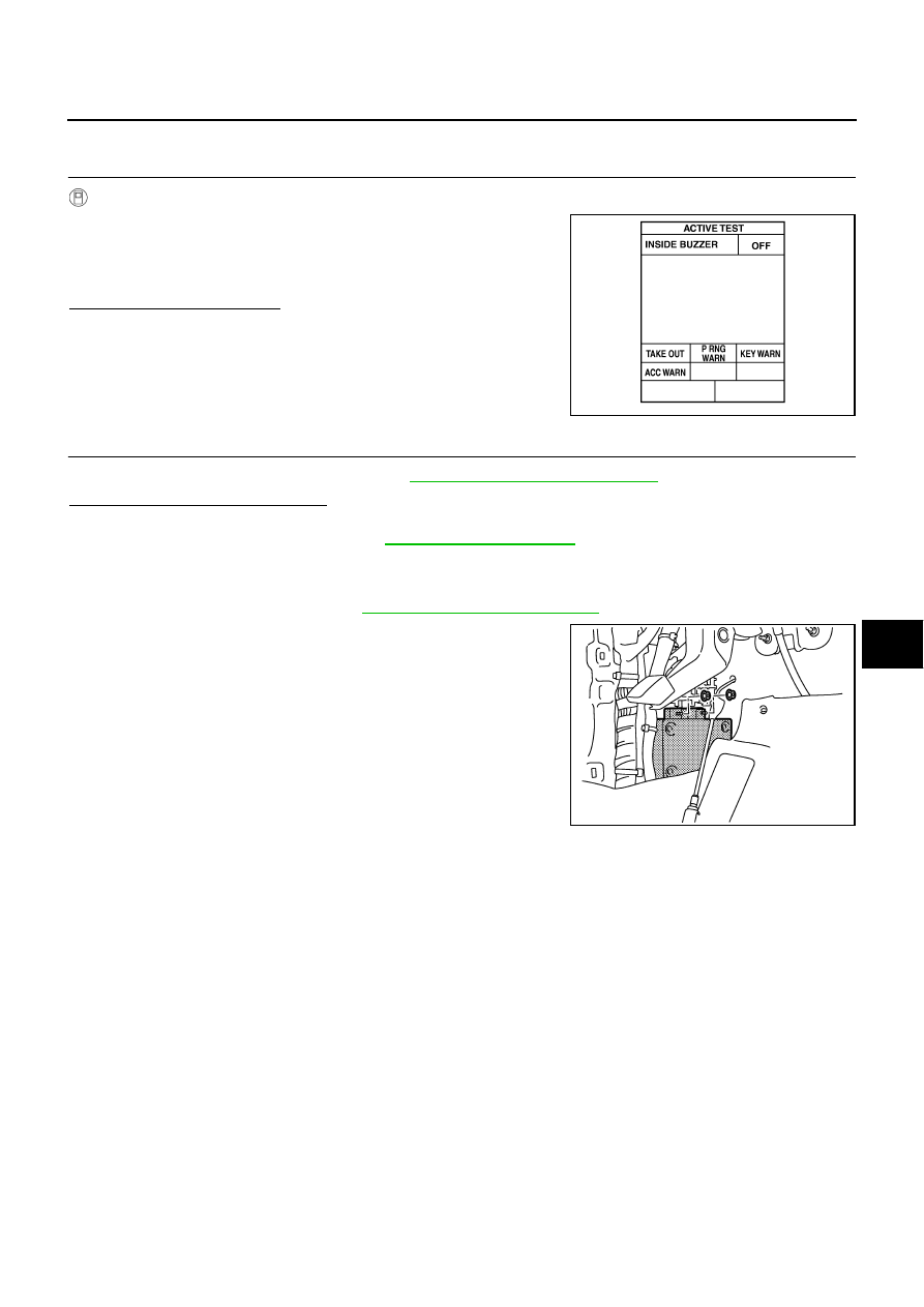
Check voltage between IPDM E/R connector and ground.
OK or NG
OK
>> Replace IPDM E/R.
NG
>> GO TO 3.
3.
CHECK HORN RELAY CIRCUIT
1.
Turn ignition switch OFF.
2.
Disconnect IPDM E/R and horn relay connector.
3.
Check continuity between IPDM E/R connector and horn relay connector.
OK or NG
OK
>> Check harness connection.
NG
>> Repair or replace harness.
Check Combination Meter Display Function
NIS001Y3
1.
CHECK METER DISPLAY
With CONSULT-II
Check the operation with (“LCD”) in the ACTIVE TEST.
OK or NG
OK
>> Meter display is OK.
NG
>> Check combination meter. Refer to
sis Mode of Combination Meter"
Terminals
Voltage (V)
(Approx.)
(+)
(–)
IPDM E/R
connector
Terminal
E9
48
Ground
Battery voltage
PIIB6219E
A
B
Continuity
IPDM E/R
connector
Terminal
Horn relay
connector
Terminal
E9
48
E20
1
Yes
PIIB6220E
Is each warning displayed on meter display?
PIIB6369E
INTELLIGENT KEY SYSTEM
BL-123
C
D
E
F
G
H
J
K
L
M
A
B
BL
Check Warning Chime Function
NIS001Y4
1.
CHECK WARNING CHIME INTO COMBINATION METER OPERATION
With CONSULT-II
1.
Check the operation with “INSIDE BUZZER” in the “ACTIVE
TEST”.
2.
Touch “TAKE OUT”, “KEY WARN”, “P RNG WARN” or “ACC
WARN” on screen.
Does warning buzzer sound?
Yes
>> Warning buzzer into combination meter is OK.
No
>> GO TO 2.
2.
CHECK OTHER WARNING CHIME OPERATION
Confirm other warning chime function. Refer to
Does other warning chime operate?
Yes
>> Warning buzzer into combination meter is OK
No
>> Check warning chime. Refer to
.
Removal and Installation of Intelligent Key Unit
NIS001Y5
REMOVAL
1.
Remove dash side finisher. Refer to
EI-37, "Removal and Installation"
.
2.
Disconnect intelligent key unit connector.
3.
Remove intelligent key unit mounting nuts, and then remove
intelligent key unit.
INSTALLATION
Installation is in the reverse order of removal.
PIIB6451E
PIIB5900E
BL-124
INTELLIGENT KEY SYSTEM
Intelligent Key Battery Replacement
NIS001Y6
DISASSEMBLY AND ASSEMBLY OF INTELLIGENT KEY
1.
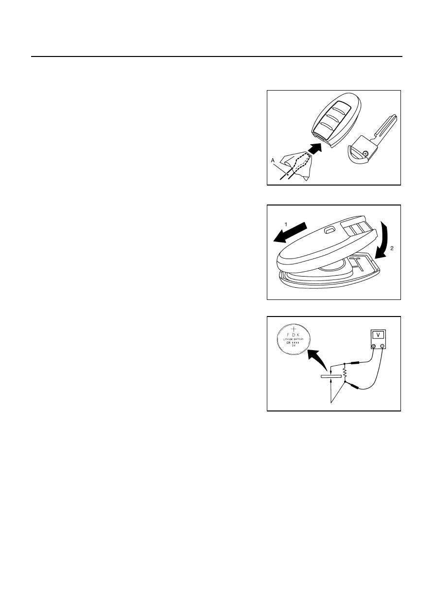
Release the lock knob at the back of the Intelligent Key and remove the mechanical key.
2.
Insert a flat-blade screwdriver (A) wrapped with a close into the
slit of the corner and twist it to separate the upper part from the
lower part.
CAUTION:
●
Be careful not to touch the circuit board or battery termi-
nal.
●
The key fob is water-resistant. However, if it does get wet,
immediately wipe it dry.
3.
Replace the battery with new one.
4.
Align the tips of the upper and lower parts, and then push them
together until it is securely closed.
CAUTION:
●
When replacing battery, be sure to keep dirt, grease, and
other foreign materials off the electrode contact area.
●
After replacing the battery, check to make sure all Intelli-
gent Key functions work normally.
INTELLIGENT KEY BATTERY INSPECTION
Check by connecting a resistance (approximately 300
Ω
) so that the
current value becomes about 10 mA.
PIIB6221E
PIIB6222E
Standard
: Approx. 2.5 - 3.0V
OCC0607D
Нет комментариевНе стесняйтесь поделиться с нами вашим ценным мнением.
Текст