Infiniti M35/M45 Y50. Manual — part 264
INTELLIGENT KEY SYSTEM/ENGINE START FUNCTION
BL-125
C
D
E
F
G
H
J
K
L
M
A
B
BL
INTELLIGENT KEY SYSTEM/ENGINE START FUNCTION
PFP:285F1
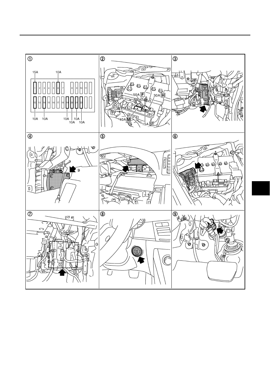
Component Parts and Harness Connector Location
NIS001Y7
1.
Fuse block (J/B) fuse layout
2.
Fuse and fusible link box
3.
BCM (View with instrument lower
panel RH removed) M1, M2
4.
Intelligent key unit (View with dash
side finisher LH removed) M32, M33
5.
PDU (View with combination meter
removed) M30, M31
6.
IPDM E/R (Engine room) E4, E9
7.
ECM (View with instrument lower
cover RH removed) M71
8.
Push-button ignition switch M27
9.
Stop lamp switch E124
PIIB5894E
BL-126
INTELLIGENT KEY SYSTEM/ENGINE START FUNCTION
System Description
NIS001Y8
●
The engine start function of Intelligent Key system is a system that makes it possible to start and stop the
engine without removing the key. It verifies the electronic ID using two-way communications when press-
ing the push-button ignition switch while carrying the Intelligent Key, which operates based on the results
of electronic ID verification for Intelligent Key using two-way communications between the Intelligent Key
and the vehicle (Intelligent Key unit).
NOTE:
The driver should always carry the intelligent key at all times.
●
Intelligent Key has 2 IDs (for Intelligent Key and for immobilizer). It can perform the door lock/unlock oper-
ation and the push-button ignition switch operation when carrying the registered Intelligent Key.
●
When the Intelligent Key battery is discharged, it can be used as emergency by inserting the Intelligent
Key to the key slot. At that time, perform the immobilizer ID verification. If it is used when carrying the
Intelligent Key, perform the Intelligent Key ID verification.
●
If the ID is successfully verified, and when push-button ignition switch is pressed, steering lock will be
released and initiating the engine will be possible.
●
If the door lock/unlock operation is performed when the Intelligent Key battery is discharged, all doors
lock/unlock can be performed by operating the driver door key cylinder using the mechanical key set into
the Intelligent Key.
●
Intelligent Key can be registered up to 4 keys (Including the standard Intelligent Key) on request from the
owner.
NOTE:
●
Refer to
BL-43, "INTELLIGENT KEY SYSTEM"
for any functions other than engine start function of
Intelligent Key system.
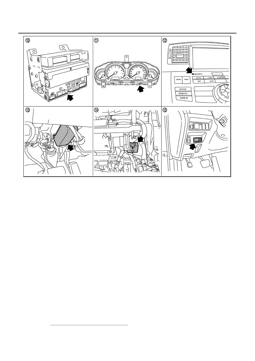
10. Unified meter and A/C amp M64,
M65
11.
Combination meter M52
12. Security indicator
(Multifunction switch) M69
13. Steering lock unit M35
(Steering column)
14. Remote keyless entry receiver
(View with instrument lower panel
RH removed) M89
15. Key slot M14
PIIB5896E
INTELLIGENT KEY SYSTEM/ENGINE START FUNCTION
BL-127
C
D
E
F
G
H
J
K
L
M
A
B
BL
PRECAUTIONS FOR INTELLIGENT KEY SYSTEM
●
In the Intelligent Key system of model Y50, the transponder (the chip for immobilizer ID verifica-
tion) is integrated into the Intelligent Key. (For the conventional models, it is integrated into the
mechanical key.) Therefore, the mechanical key cannot perform the ID verification, and thus it can-
not start the engine. Instead of it, the immobilizer ID verification can be performed by inserting the
Intelligent Key into the key slot, and then it can start the engine.
●
When registering the Intelligent Key, 2 registration procedures (immobilizer ID registration and
Intelligent Key ID registration) should be performed. The immobilizer ID registration is the proce-
dure that registers the ID stored into the transponder (integrated into Intelligent Key) to the BCM.
The Intelligent Key ID registration is the procedure that registers the ID to the Intelligent Key unit.
Each registration is a different procedure.
●
When performing the Intelligent Key ID registration only, the engine cannot be started by inserting
the key into the key slot. When performing the engine immobilizer ID registration only, the engine
cannot be started by the operation when carrying the key. The registrations of both systems
should be performed.
Operation Description
NIS001Y9
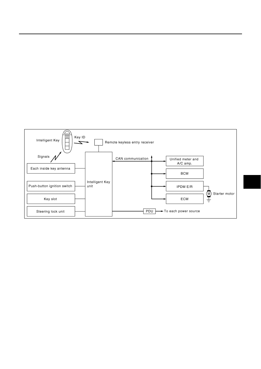
SYSTEM DIAGRAM
OPERATION WHEN INTELLIGENT KEY IS CARRIED
Description
1.
When the push-button switch is pressed, the Intelligent Key unit signals the inside key antenna and sends
the request signal to the Intelligent Key.
2.
The Intelligent Key receives the request signal and sends the Intelligent Key ID signal to the Intelligent
Key unit via the remote keyless entry receiver.
3.
The Intelligent Key receives the Intelligent Key ID signal and verifies it with the registered ID.
4.
If the ID is successfully verified, the Intelligent Key unit sends the steering unlock signal to the steering
lock unit. Then, it sends each power supply request signal to PDU (Power Distribution Unit) after unlock-
ing the steering lock.
5.
If the Intelligent Key unit judges that the engine start condition is satisfied, it sends the starter request sig-
nal via CAN communication to IPDM E/R and turns the starter motor relay ON.
6.
The steering lock unit unlocks the steering lock when receiving the signal. PDU starts the power supply
distribution according to the push-button ignition switch operation when receiving the signal. If it enters the
engine start permission mode, the power supply is supplied from PDU to the starter motor relay and the
cranking is started.
CAUTION:
If a malfunction is detected in the Intelligent Key system, the “KEY” warning lamp in the combina-
tion meter illuminates for 15 seconds. At that time, the engine cannot be started.
7.
When Intelligent Key unit received feedback signal from ECM acknowledging the engine has been initi-
ated, the Intelligent Key unit sends a stop signal to IPDM E/R and stops the cranking by turning OFF the
PIIB6272E

BL-128
INTELLIGENT KEY SYSTEM/ENGINE START FUNCTION
starter motor relay. (If the engine initiating has failed, the cranking will stop automatically within 5 sec-
onds.)
CAUTION:
When the Intelligent Key is carried outside of the vehicle (inside key antenna detection area) with
the power supply in ACC or ON position, even if the engine start condition* is satisfied, the engine
cannot be started.
*: For the engine start condition, refer to
BL-128, "PUSH-BUTTON IGNITION SWITCH OPERATION PROCE-
Operation Range
Engine can be started when Intelligent Key is inside the vehicle. However, sometimes engine might not start
when Intelligent Key is on instrument panel or in glove box.
OPERATION WHEN KEY SLOT IS USED
When the Intelligent Key battery is discharged, it performs the immobilizer ID verification between the inte-
grated transponder and BCM by inserting the Intelligent Key into the key slot, and then the engine can be
started.
For details relating to starting the engine using key slot, refer to
BL-244, "IVIS (INFINITI VEHICLE IMMOBI-
PUSH-BUTTON IGNITION SWITCH OPERATION PROCEDURE
The power supply position changing operation can be performed with the following operation.
NOTE:
●
When an Intelligent Key is within the detection area of inside key antenna and when it is inserted to the
key slot, it is equivalent to the operations below.
●
When starting the engine, the Intelligent Key unit monitors the engine start conditions (brake pedal operat-
ing condition, A/T selector lever position, and vehicle speed).
●
Unless each start condition is fulfilled, the engine will not respond regardless of how many times the
engine switch is pushed. At that time, illumination repeats the position in the order of LOCK
→
AC-
C
→
ON
→
LOCK.
Power supply position
Engine start/stop condition
Push-button ignition switch
operation frequency
Brake pedal
A/T selector lever position
LOCK
→
ACC
Not depressed
(When A/T selector lever is in any
position other than P or N, there
will be no effect even if it is
depressed.)
Any position other than P or N
(When the brake pedal is not
depressed, there will be no effect
even if the A/T selector lever is in
P or N position.)
1
LOCK
→
ACC
→
ON
Not depressed
(When A/T selector lever is in any
position other than P or N, there
will be no effect even if it is
depressed.)
Any position other than P or N
(When the brake pedal is not
depressed, there will be no effect
even if the A/T selector lever is in
P or N position.)
2
LOCK
→
ACC
→
ON
→
LOCK
Not depressed
(When A/T selector lever is in any
position other than P or N, there
will be no effect even if it is
depressed.)
Any position other than P or N
(When the brake pedal is not
depressed, there will be no effect
even if the A/T selector lever is in
P or N position.)
3
LOCK
→
START
ACC
→
START
ON
→
START
(Engine start)
Depressed
P or N position (*1)
1
[If the switch is pushed once,
the engine starts from any
power supply position (LOCK,
ACC, and ON)]
Engine is running
→
LOCK
(Engine stop)
—
P position
1
Нет комментариевНе стесняйтесь поделиться с нами вашим ценным мнением.
Текст