Infiniti M35/M45 Y50. Manual — part 549
FUEL INJECTOR
EC-669
[VQ35DE]
C
D
E
F
G
H
I
J
K
L
M
A
EC
FUEL INJECTOR
PFP:16600
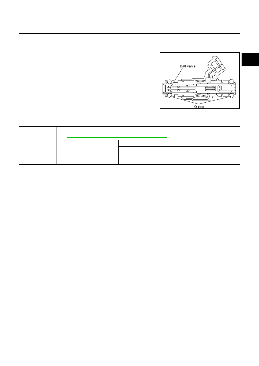
Component Description
NBS0057T
The fuel injector is a small, precise solenoid valve. When the ECM
supplies a ground to the fuel injector circuit, the coil in the fuel injec-
tor is energized. The energized coil pulls the ball valve back and
allows fuel to flow through the fuel injector into the intake manifold.
The amount of fuel injected depends upon the injection pulse dura-
tion. Pulse duration is the length of time the fuel injector remains
open. The ECM controls the injection pulse duration based on
engine fuel needs.
CONSULT-II Reference Value in Data Monitor Mode
NBS0057U
Specification data are reference values.
SEF375Z
MONITOR ITEM
CONDITION
SPECIFICATION
B/FUEL SCHDL
See
EC-143, "TROUBLE DIAGNOSIS - SPECIFICATION VALUE"
INJ PULSE-B1
INJ PULSE-B2
●
Engine: After warming up
●
Selector lever: P or N
●
Air conditioner switch: OFF
●
No load
Idle
2.0 - 3.0 msec
2,000 rpm
1.9 - 2.9 msec
EC-670
[VQ35DE]
FUEL INJECTOR
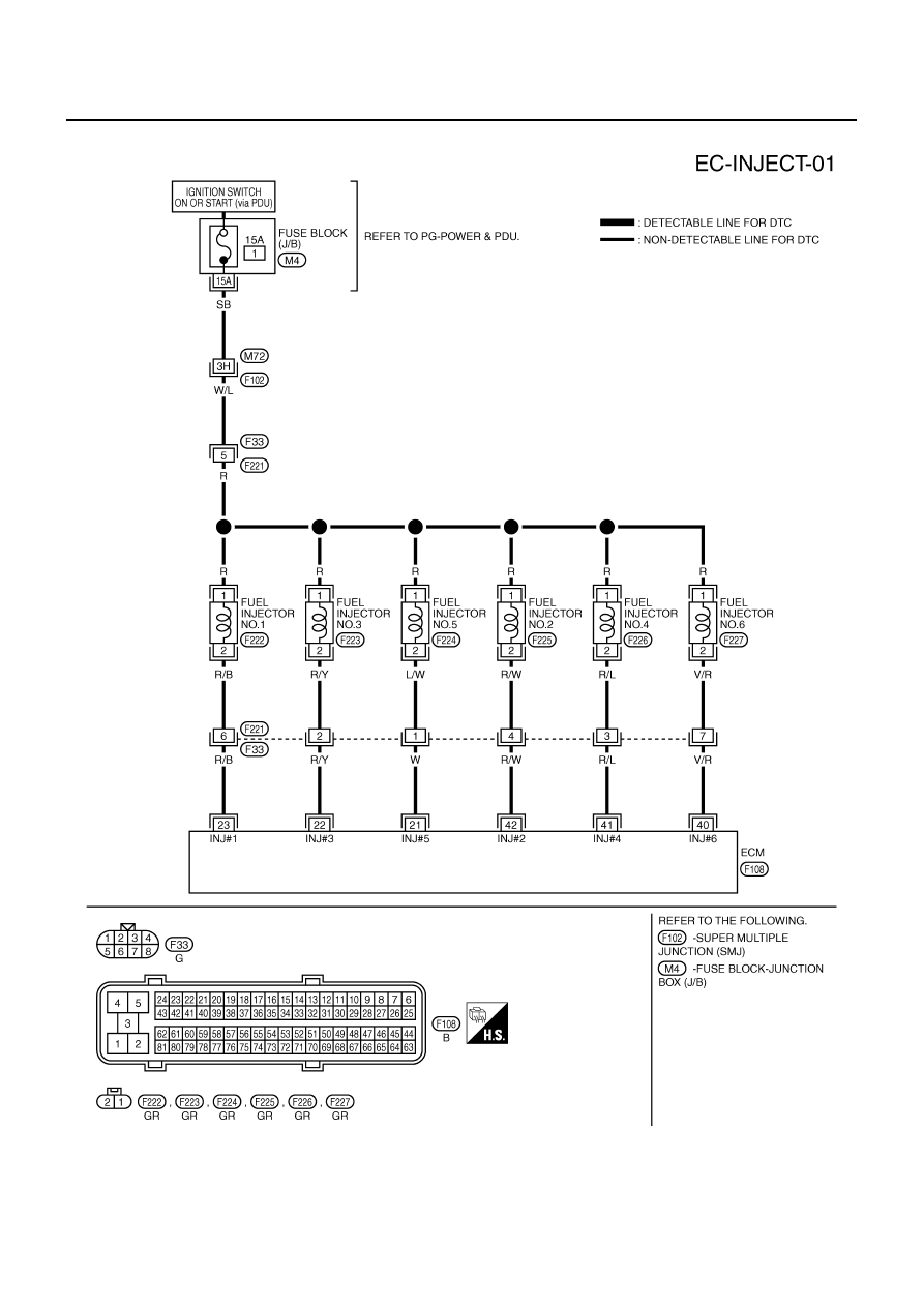
Wiring Diagram
NBS0057V
TBWT0996E
FUEL INJECTOR
EC-671
[VQ35DE]
C
D
E
F
G
H
I
J
K
L
M
A
EC
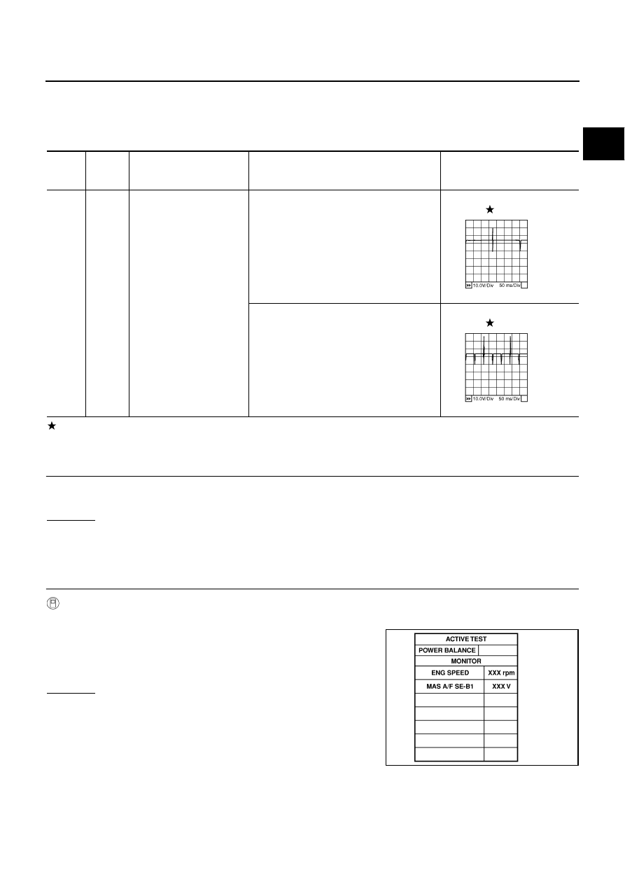
Specification data are reference values and are measured between each terminal and ground.
Pulse signal is measured by CONSULT-II.
CAUTION:
Do not use ECM ground terminals when measuring input/output voltage. Doing so may result in dam-
age to the ECM's transistor. Use a ground other than ECM terminals, such as the ground.
: Average voltage for pulse signal (Actual pulse signal can be confirmed by oscilloscope.)
Diagnostic Procedure
NBS0057W
1.
INSPECTION START
Turn ignition switch to START.
Is any cylinder ignited?
Yes or No
Yes (With CONSULT-II)>>GO TO 2.
Yes (Without CONSULT-II)>>GO TO 3.
No
>> GO TO 6.
2.
CHECK OVERALL FUNCTION
With CONSULT-II
1.
Start engine.
2.
Perform “POWER BALANCE” in “ACTIVE TEST” mode with
CONSULT-II.
3.
Make sure that each circuit produces a momentary engine
speed drop.
OK or NG
OK
>> INSPECTION END
NG
>> GO TO 3.
TER-
MINAL
NO.
WIRE
COLOR
ITEM
CONDITION
DATA (DC Voltage)
21
22
23
40
41
42
W
R/Y
R/B
V/R
R/L
R/W
Fuel injector No. 5
Fuel injector No. 3
Fuel injector No. 1
Fuel injector No. 6
Fuel injector No. 4
Fuel injector No. 2
[Engine is running]
●
Warm-up condition
●
Idle speed
NOTE:
The pulse cycle changes depending on rpm
at idle
BATTERY VOLTAGE
(11 - 14V)
[Engine is running]
●
Warm-up condition
●
Engine speed: 2,000 rpm
BATTERY VOLTAGE
(11 - 14V)
PBIB0042E
PBIB0043E
PBIB0133E
EC-672
[VQ35DE]
FUEL INJECTOR
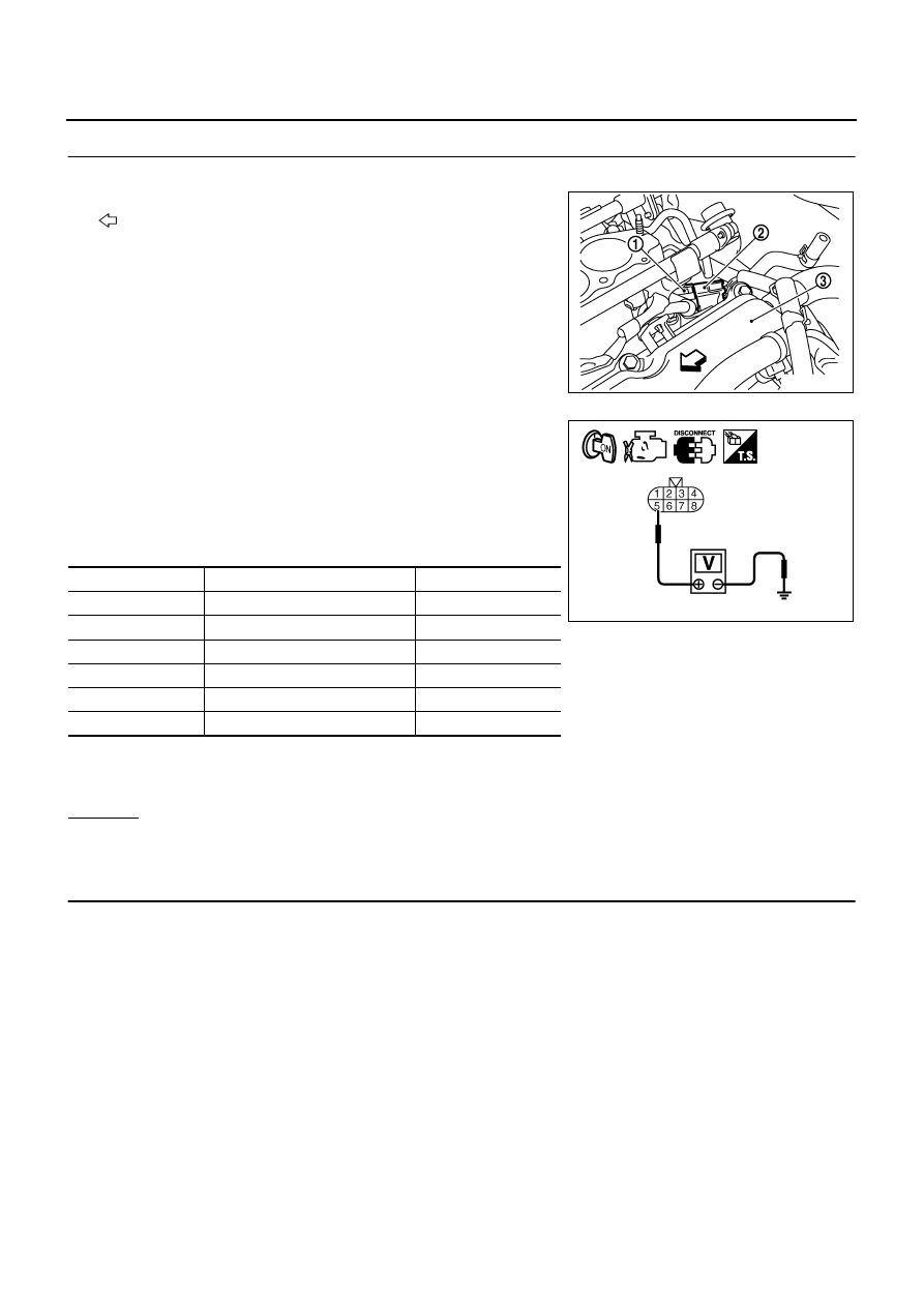
3.
CHECK FUNCTION OF FUEL INJECTOR-I
1.
Turn ignition switch OFF.
2.
Disconnect harness connectors F221 (1), F33 (2).
–
: Vehicle front
–
Cylinder head (bank 2) (3)
3.
Turn ignition switch ON.
4.
Check voltage between harness connector F33 terminal 5 and
ground with CONSULT-II or tester.
5.
Turn ignition switch OFF.
6.
Disconnect ECM harness connector.
7.
Check harness continuity between the following terminals.
8.
Also check harness for short to ground and short to power.
OK or NG
OK
>> GO TO 5.
NG
>> GO TO 4.
4.
DETECT MALFUNCTIONING PART
Check the following.
●
Harness connectors M72, F102
●
Harness connectors F33
●
Fuse block (J/B) connector M4
●
15A fuse
●
Harness for open or short between harness connector F33 and fuse
●
Harness for open or short between harness connector F33 and ECM
>> Repair open circuit or short to ground or short to power in harness or connectors.
PBIB2785E
Voltage: Battery voltage
Cylinder
Harness connector F33 terminal
ECM terminal
1
6
23
2
4
42
3
2
22
4
3
41
5
1
21
6
7
40
Continuity should exist.
PBIB2323E
Нет комментариевНе стесняйтесь поделиться с нами вашим ценным мнением.
Текст