Infiniti M35/M45 Y50. Manual — part 579
BASIC SERVICE PROCEDURE
EC-789
[VK45DE]
C
D
E
F
G
H
I
J
K
L
M
A
EC
5.
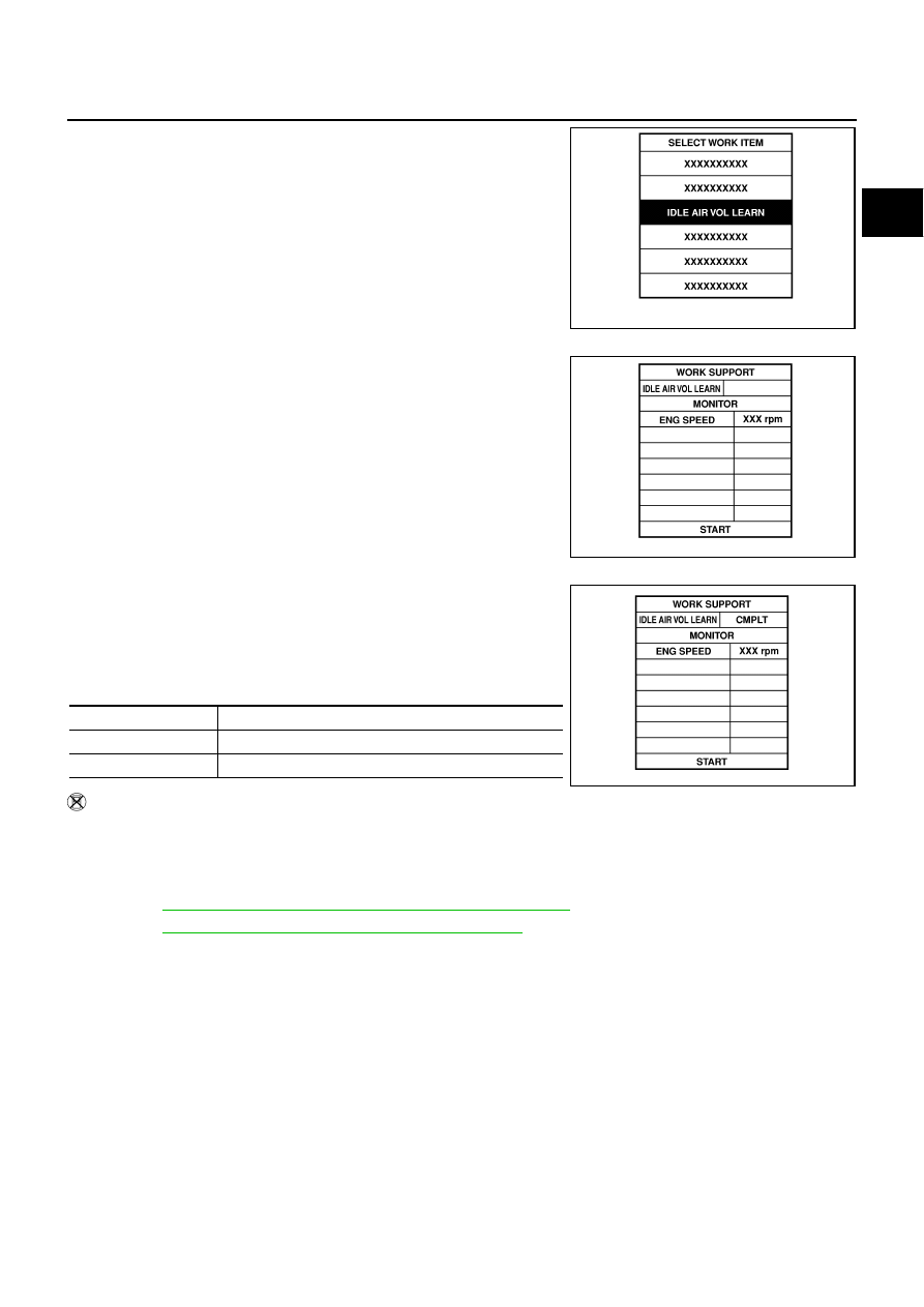
Select “IDLE AIR VOL LEARN” in “WORK SUPPORT” mode.
6.
Touch “START” and wait 20 seconds.
7.
Make sure that “CMPLT” is displayed on CONSULT-II screen. If
“CMPLT” is not displayed, Idle Air Volume Learning will not be
carried out successfully. In this case, find the cause of the inci-
dent by referring to the DIAGNOSTIC PROCEDURE below.
8.
Rev up the engine two or three times and make sure that idle
speed and ignition timing are within the specifications.
Without CONSULT-II
NOTE:
●
It is better to count the time accurately with a clock.
●
It is impossible to switch the diagnostic mode when an accelerator pedal position sensor circuit
has a malfunction.
1.
Perform
EC-788, "Accelerator Pedal Released Position Learning"
2.
Perform
EC-788, "Throttle Valve Closed Position Learning"
3.
Start engine and warm it up to normal operating temperature.
4.
Check that all items listed under the topic PREPARATION (previously mentioned) are in good order.
5.
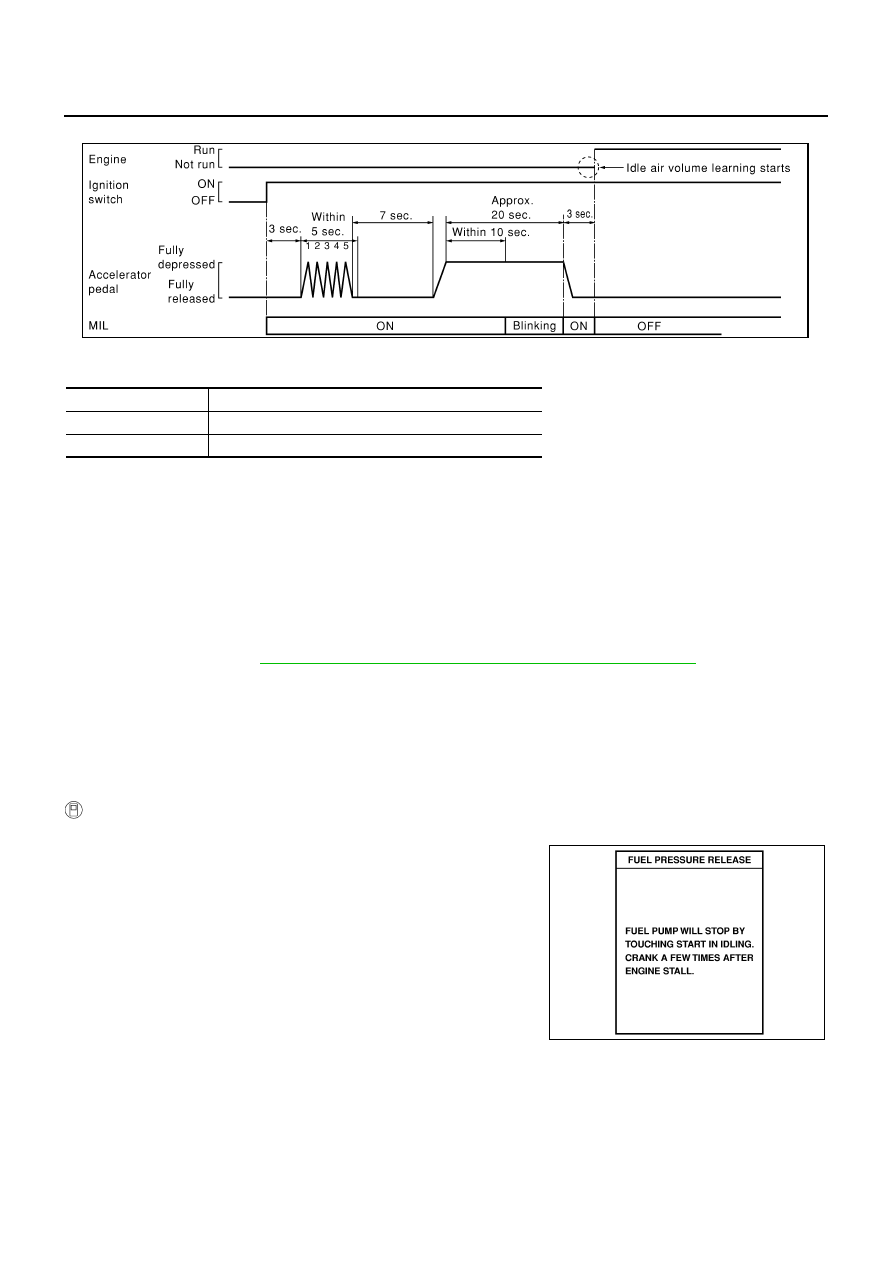
Turn ignition switch OFF and wait at least 10 seconds.
6.
Confirm that accelerator pedal is fully released, turn ignition switch ON and wait 3 seconds.
7.
Repeat the following procedure quickly five times within 5 seconds.
a.
Fully depress the accelerator pedal.
b.
Fully release the accelerator pedal.
8.
Wait 7 seconds, fully depress the accelerator pedal and keep it for approx. 20 seconds until the MIL stops
blinking and turned ON.
9.
Fully release the accelerator pedal within 3 seconds after the MIL turned ON.
10. Start engine and let it idle.
SEF217Z
SEF454Y
ITEM
SPECIFICATION
Idle speed
650
±
50 rpm (in P or N position)
Ignition timing
12
±
5
°
BTDC (in P or N position)
MBIB0238E
EC-790
[VK45DE]
BASIC SERVICE PROCEDURE
11. Wait 20 seconds.
12. Rev up the engine two or three times and make sure that idle speed and ignition timing are within the
specifications.
13. If idle speed and ignition timing are not within the specification, Idle Air Volume Learning will not be carried
out successfully. In this case, find the cause of the incident by referring to the Diagnostic Procedure below.
DIAGNOSTIC PROCEDURE
If idle air volume learning cannot be performed successfully, proceed as follows:
1.
Check that throttle valve is fully closed.
2.
Check PCV valve operation.
3.
Check that downstream of throttle valve is free from air leakage.
4.
When the above three items check out OK, engine component parts and their installation condi-
tion are questionable. Check and eliminate the cause of the incident.
It is useful to perform
EC-847, "TROUBLE DIAGNOSIS - SPECIFICATION VALUE"
5.
If any of the following conditions occur after the engine has started, eliminate the cause of the
incident and perform Idle Air Volume Learning all over again:
●
Engine stalls.
●
Erroneous idle.
Fuel Pressure Check
NBS005AD
FUEL PRESSURE RELEASE
With CONSULT-II
1.
Turn ignition switch ON.
2.
Perform “FUEL PRESSURE RELEASE” in “WORK SUPPORT”
mode with CONSULT-II.
3.
Start engine.
4.
After engine stalls, crank it two or three times to release all fuel
pressure.
5.
Turn ignition switch OFF.
ITEM
SPECIFICATION
Idle speed
650
±
50 rpm (in P or N position)
Ignition timing
12
±
5
°
BTDC (in P or N position)
SEC897C
SEF214Y
BASIC SERVICE PROCEDURE
EC-791
[VK45DE]
C
D
E
F
G
H
I
J
K
L
M
A
EC
Without CONSULT-II
1.
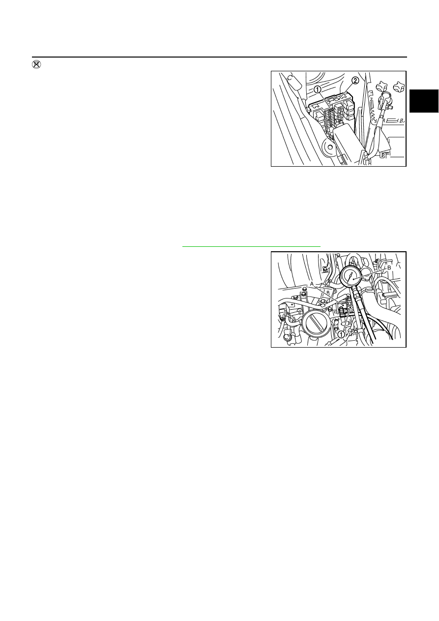
Remove fuel pump fuse (1) located in IPDM E/R (2).
2.
Start engine.
3.
After engine stalls, crank it 2 or 3 times to release all fuel pres-
sure.
4.
Turn ignition switch OFF.
5.
Reinstall fuel pump fuse after servicing fuel system.
FUEL PRESSURE CHECK
CAUTION:
Before disconnecting fuel line, release fuel pressure from fuel line to eliminate danger.
NOTE:
●
Prepare pans or saucers under the disconnected fuel line because the fuel may spill out. The fuel
pressure cannot be completely released because Y50 models do not have fuel return system.
●
Use Fuel Pressure Gauge Kit (J-44321) to check fuel pressure.
1.
Release fuel pressure to zero. Refer to
EC-790, "FUEL PRESSURE RELEASE"
2.
Install the inline fuel quick disconnect fitting A between fuel
damper (1) and fuel tube.
3.
Connect the fuel pressure gauge B (quick connect adapter
hose) to the inline fuel quick disconnect fitting.
4.
Turn ignition switch ON and check for fuel leakage.
5.
Start engine and check for fuel leakage.
6.
Read the indication of fuel pressure gauge.
7.
If result is unsatisfactory, go to next step.
8.
Check the following.
●
Fuel hoses and fuel tubes for clogging
●
Fuel filter for clogging
●
Fuel pump
●
Fuel pressure regulator for clogging
If OK, replace fuel level sensor unit, fuel filter and fuel pump assembly.
If NG, repair or replace.
PBIB2697E
At idling:
Approximately 350 kPa (3.57 kg/cm
2
, 51 psi)
PBIB2720E
EC-792
[VK45DE]
TROUBLE DIAGNOSIS
TROUBLE DIAGNOSIS
PFP:00004
Trouble Diagnosis Introduction
NBS005AE
INTRODUCTION
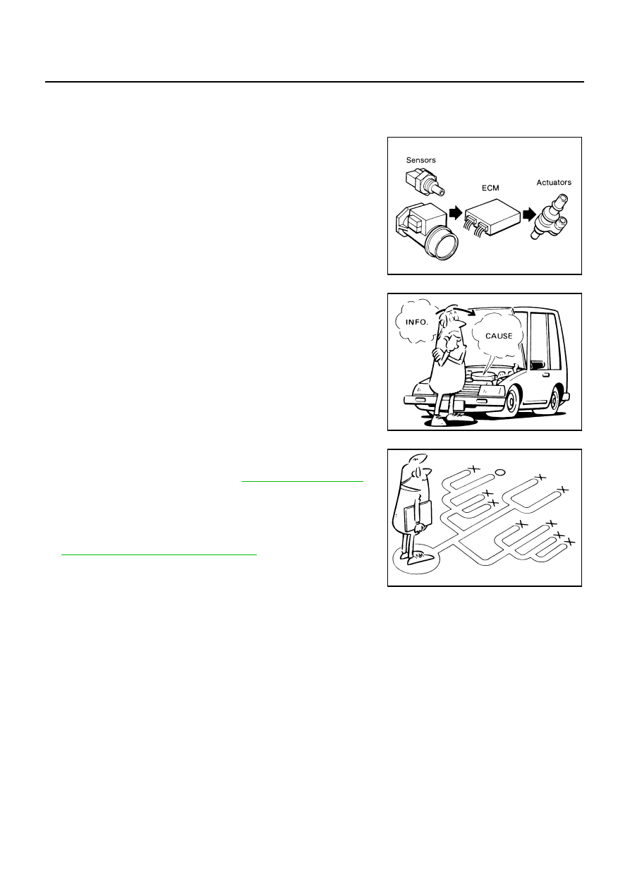
The engine has an ECM to control major systems such as fuel con-
trol, ignition control, idle air control system, etc. The ECM accepts
input signals from sensors and instantly drives actuators. It is essen-
tial that both input and output signals are proper and stable. At the
same time, it is important that there are no malfunctions such as vac-
uum leaks, fouled spark plugs, or other malfunctions with the engine.
It is much more difficult to diagnose an incident that occurs intermit-
tently rather than continuously. Most intermittent incidents are
caused by poor electric connections or improper wiring. In this case,
careful checking of suspected circuits may help prevent the replace-
ment of good parts.
A visual check only may not find the cause of the incidents. A road
test with CONSULT-II (or GST) or a circuit tester connected should
be performed. Follow the Work Flow on
.
Before undertaking actual checks, take a few minutes to talk with a
customer who approaches with a driveability complaint. The cus-
tomer can supply good information about such incidents, especially
intermittent ones. Find out what symptoms are present and under
what conditions they occur. A Diagnostic Worksheet like the example
on
EC-796, "DIAGNOSTIC WORKSHEET"
should be used.
Start your diagnosis by looking for conventional malfunctions first.
This will help troubleshoot driveability malfunctions on an electroni-
cally controlled engine vehicle.
MEF036D
SEF233G
SEF234G
Нет комментариевНе стесняйтесь поделиться с нами вашим ценным мнением.
Текст