Infiniti M35/M45 Y50. Manual — part 919
TURN SIGNAL AND HAZARD WARNING LAMPS
LT-221
C
D
E
F
G
H
I
J
L
M
A
B
LT
How to Perform Trouble Diagnoses
NKS003RR
1.
Confirm the symptom or customer complaint.
2.
Understand operation description and function description. Refer to
.
3.
Perform the Preliminary Check. Refer to
4.
Check symptom and repair or replace the cause of malfunction.
5.
Do turn signal and hazard warning lamps operate normally? If YES, GO TO 6. If NO, GO TO 4.
6.
INSPECTION END
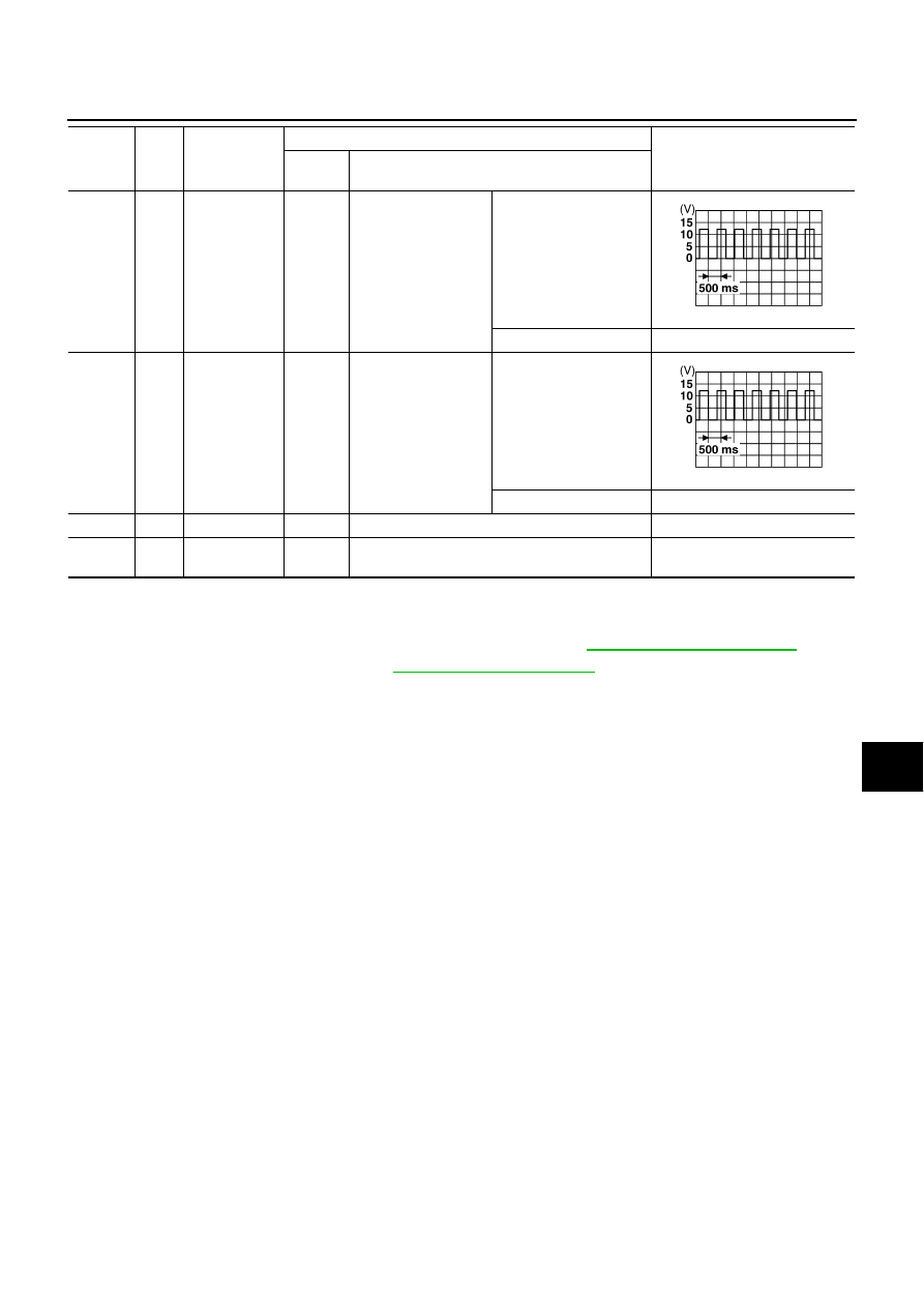
45
G
Flasher output
(Left)
ON
Turn signal switch
To left
OFF
Approx. 0 V
46
L
Flasher output
(Right)
ON
Turn signal switch
To right
OFF
Approx. 0 V
52
B
Ground
ON
—
Approx. 0 V
55
W
Battery power
supply
OFF
—
Battery voltage
Terminal
No.
Wire
color
Signal name
Measuring condition
Reference value
Ignition
switch
Operation or condition
SKIA3009J
SKIA3009J
LT-222
TURN SIGNAL AND HAZARD WARNING LAMPS
Preliminary Check
NKS003RS
CHECK POWER SUPPLY AND GROUND CIRCUIT
1.
CHECK FUSES AND FUSIBLE LINK
Check for blown fuses and fusible link.
LT-216, "Wiring Diagram — TURN —"
.
OK or NG
OK
>> GO TO 2.
NG
>> If fuse or fusible link is blown, be sure to eliminate cause of malfunction before installing new fuse
PG-3, "POWER SUPPLY ROUTING CIRCUIT"
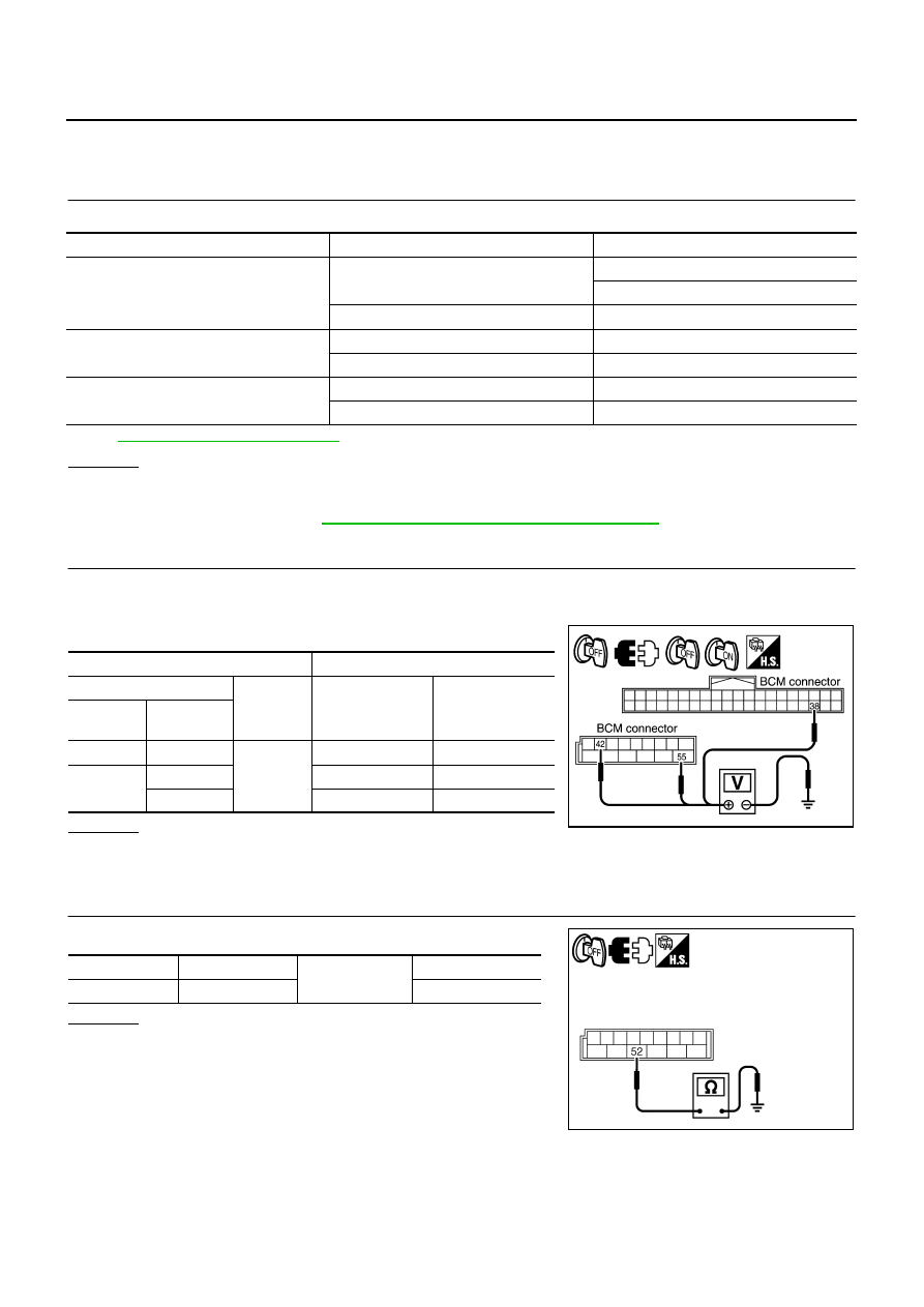
2.
CHECK POWER SUPPLY CIRCUIT
1.
Turn ignition switch OFF.
2.
Disconnect BCM connector.
3.
Check voltage between BCM harness connector and ground.
OK or NG
OK
>> GO TO 3.
NG
>> Repair harness or connector.
3.
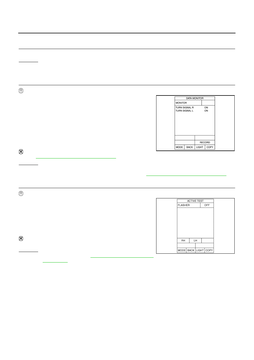
CHECK GROUND CIRCUIT
Check continuity between BCM harness connector and ground.
OK or NG
OK
>> INSPECTION END
NG
>> Repair harness or connector.
Unit
Power source
Fuse and fusible link No.
BCM
Battery
F
21
Ignition switch ON or START position
1
Combination meter
Battery
21
Ignition switch ON or START position
14
Unified meter and A/C amp.
Battery
19
Ignition switch ON or START position
12
Terminal
Ignition switch position
(+)
(-)
OFF
ON
BCM
connector
Terminal
M1
38
Ground
Approx. 0 V
Battery voltage
M2
42
Battery voltage
Battery voltage
55
Battery voltage
Battery voltage
PKIB5199E
BCM connector
Terminal
Ground
Continuity
M2
52
Yes
SKIB5125E

TURN SIGNAL AND HAZARD WARNING LAMPS
LT-223
C
D
E
F
G
H
I
J
L
M
A
B
LT
CONSULT-II Functions (BCM)
NKS003RT
CONSULT-II can display each diagnostic item using the diagnostic test mode shown following.
CONSULT-II BASIC OPERATION
Refer to
GI-38, "CONSULT-II Start Procedure"
.
DATA MONITOR
Operation Procedure
1.
Touch “FLASHER” on “SELECT TEST ITEM” screen.
2.
Touch “DATA MONITOR” on “SELECT DIAG MODE” screen.
3.
Touch either “ALL SIGNALS” or “SELECTION FROM MENU” on the “SELECT MONITOR ITEM” screen.
4.
When “SELECTION FROM MENU” is selected, touch items to be monitored. When “ALL SIGNALS” is
selected, all the items will be monitored.
5.
Touch “START”.
6.
Touch “RECORD” while monitoring, then the status of the monitored item can be recorded. To stop
recording, touch “STOP”.
Display Item List
ACTIVE TEST
Operation Procedure
1.
Touch “FLASHER” on “SELECT TEST ITEM” screen.
2.
Touch “ACTIVE TEST” on “SELECT DIAG MODE” screen.
3.
Touch item to be tested and check operation of the selected item.
4.
During the operation check, touching “BACK” deactivates the operation.
Display Item List
BCM diagnosis part
Diagnosis mode
Description
FLASHER
DATA MONITOR
Displays BCM input data in real time.
ACTIVE TEST
Operation of electrical loads can be checked by sending driving signal to them.
ALL SIGNALS
Monitors all the signals.
SELECTION FROM MENU
Selects items and monitor them.
Monitor item
Contents
IGN ON SW
“ON/OFF”
Displays “IGN position (ON)/OFF, ACC position (OFF)” judged from the ignition switch signal.
HAZARD SW
“ON/OFF”
Displays “hazard ON (ON)/hazard OFF (OFF)” status, determined from hazard switch signal.
TURN SIGNAL R
“ON/OFF”
Displays “turn right (ON)/other (OFF)” status, determined from lighting switch signal.
TURN SIGNAL L
“ON/OFF”
Displays “turn left (ON)/other (OFF)” status, determined from lighting switch signal.
Test item
Description
FLASHER (RIGHT)
Turn signal lamp (right) can be operated by any ON-OFF operations.
FLASHER (LEFT)
Turn signal lamp (left) can be operated by any ON-OFF operations.
LT-224
TURN SIGNAL AND HAZARD WARNING LAMPS
Turn Signal Lamp Does Not Operate
NKS003RU
1.
CHECK BULB
Check bulb standard of each turn signal lamp is correct.
OK or NG
OK
>> GO TO 2.
NG
>> Replace turn signal lamp bulb.
2.
CHECK COMBINATION SWITCH INPUT SIGNAL
With CONSULT-II
1.
Select “BCM” on CONSULT-II. Select “FLASHER” on “SELECT
TEST ITEM” screen.
2.
Select “DATA MONITOR” on “SELECT DIAG MODE” screen.
Make sure “TURN SIGNAL R” and “TURN SIGNAL L” turns ON-
OFF linked with operation of lighting switch.
Without CONSULT-II
Refer to
LT-239, "Combination Switch Inspection"
OK or NG
OK
>> GO TO 3.
NG
>> Check combination switch (lighting switch). Refer to
LT-239, "Combination Switch Inspection"
3.
ACTIVE TEST
With CONSULT-II
1.
Select “BCM” on CONSULT-II. Select “FLASHER” on “SELECT
TEST ITEM” screen.
2.
Select “ACTIVE TEST” on “SELECT DIAG MODE” screen.
Select “FLASHER” on “SELECT TEST ITEM” screen.
3.
Make sure operation of turn signal lamps.
Without CONSULT-II
GO TO 4.
OK or NG
OK
>> Replace BCM. Refer to
BCS-15, "Removal and Installa-
NG
>> GO TO 4.
When lighting switch is
TURN RH position
: TURN SIGNAL R ON
When lighting switch is
TURN LH position
: TURN SIGNAL L ON
PKIA7600E
Turn signal lamp should operate.
SKIA6190E
Нет комментариевНе стесняйтесь поделиться с нами вашим ценным мнением.
Текст