Infiniti M35/M45 Y50. Manual — part 917
TURN SIGNAL AND HAZARD WARNING LAMPS
LT-213
C
D
E
F
G
H
I
J
L
M
A
B
LT
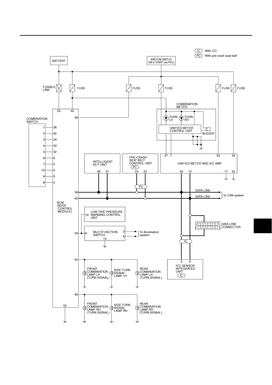
LH Turn Signal Lamp
When turn signal switch is moved to left position, BCM receives input signal requesting left turn signals to
flash. BCM then supplies power
●
through BCM terminal 45
●
to front combination lamp LH (turn signal) terminal 10
●
to side turn signal lamp LH terminal 1, and
●
to rear combination lamp LH (turn signal) terminal 3.
Ground is supplied
●
to front combination lamp LH (turn signal) terminal 9
●
to side turn signal lamp LH terminal 2
●
through grounds E22 and E43,
●
to rear combination lamp LH (turn signal) terminal 4
●
through grounds B5, B40 and B131.
The BCM also supplies input to unified meter and A/C amp. terminals 56 and 72 across the CAN communica-
tion lines.
The unified meter and A/C amp. which received the turn indicator signal makes the left turn signal indicator
turn on in combination meter.
With power and input supplied, the BCM controls the flashing of the LH turn signal lamps.
RH Turn Signal Lamp
When turn signal switch is moved to right position, BCM receives input signal requesting right turn signals to
flash. BCM then supplies power
●
through BCM terminal 46
●
to front combination lamp RH (turn signal) terminal 10
●
to side turn signal lamp RH terminal 1, and
●
to rear combination lamp RH (turn signal) terminal 3.
Ground is supplied
●
to front combination lamp RH (turn signal) terminal 9
●
to side turn signal lamp RH terminal 2
●
through grounds E22 and E43,
●
to rear combination lamp RH (turn signal) terminal 4
●
through grounds B5, B40 and B131.
The BCM also supplies input to unified meter and A/C amp. terminals 56 and 72 across the CAN communica-
tion lines.
The unified meter and A/C amp. which received the turn indicator signal makes the right turn signal indicator
turn on in combination meter.
With power and input supplied, the BCM controls the flashing of the RH turn signal lamps.
HAZARD LAMP OPERATION
Power is supplied at all times
●
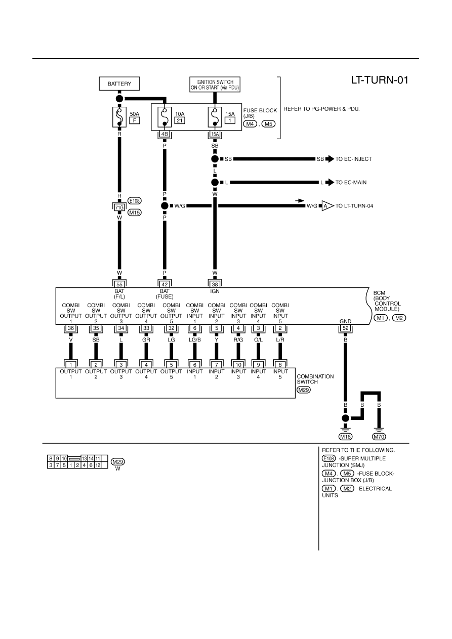
through 50A fusible link (letter F, located in fuse, fusible link and relay block)
●
to BCM terminal 55,
●
through 10A fuse [No. 21, located in fuse block (J/B)]
●
to BCM terminal 42
●
to combination meter terminal 23,
●
through 10A fuse [No. 19, located in fuse block (J/B)]
●
to unified meter and A/C amp. terminal 54.
When the hazard switch is depressed, ground is supplied
●
to BCM terminal 29
●
through multifunction switch terminal 6.
Ground is supplied
●
to multifunction switch terminal 14
LT-214
TURN SIGNAL AND HAZARD WARNING LAMPS
●
to BCM terminal 52
●
to combination meter terminals 9, 10 and 11
●
to unified meter and A/C amp. terminals 55 and 71
●
through grounds M16 and M70.
BCM then supplies power
●
through BCM terminal 45
●
to front combination lamp LH (turn signal) terminal 10
●
to side turn signal lamp LH terminal 1
●
to rear combination lamp LH (turn signal) terminal 3,
●
through BCM terminal 46
●
to front combination lamp RH (turn signal) terminal 10
●
to side turn signal lamp RH terminal 1
●
to rear combination lamp RH (turn signal) terminal 3.
Ground is supplied
●
to front combination lamp LH (turn signal) terminal 9
●
to front combination lamp RH (turn signal) terminal 9
●
to side turn signal lamp LH terminal 2
●
to side turn signal lamp RH terminal 2
●
through grounds E22 and E43,
●
to rear combination lamp LH (turn signal) terminal 4
●
to rear combination lamp RH (turn signal) terminal 4
●
through grounds B5, B40 and B131.
The BCM also supplies input to unified meter and A/C amp. terminals 56 and 72 across the CAN communica-
tion lines.
The unified meter and A/C amp. which received the turn indicator signal makes the left and right turn signal
indicator turn on in combination meter.
With power and input supplied, the BCM controls the flashing of the hazard warning lamps.
COMBINATION SWITCH READING FUNCTION
Refer to
BCS-3, "COMBINATION SWITCH READING FUNCTION"
CAN Communication System Description
NKS003RM
CAN (Controller Area Network) is a serial communication line for real time application. It is an on-vehicle mul-
tiplex communication line with high data communication speed and excellent error detection ability. Many elec-
tronic control units are equipped onto a vehicle, and each control unit shares information and links with other
control units during operation (not independent). In CAN communication, control units are connected with 2
communication lines (CAN H line, CAN L line) allowing a high rate of information transmission with less wiring.
Each control unit transmits/receives data but selectively reads required data only.
CAN Communication Unit
NKS003RN
Refer to
TURN SIGNAL AND HAZARD WARNING LAMPS
LT-215
C
D
E
F
G
H
I
J
L
M
A
B
LT
Schematic
NKS003RO
TKWT3380E
LT-216
TURN SIGNAL AND HAZARD WARNING LAMPS
Wiring Diagram — TURN —
NKS003RP
TKWT3381E
Нет комментариевНе стесняйтесь поделиться с нами вашим ценным мнением.
Текст