Infiniti M35/M45 Y50. Manual — part 339
ACTUATOR AND ELECTRIC UNIT (ASSEMBLY)
BRC-57
[VDC/TCS/ABS]
C
D
E
G
H
I
J
K
L
M
A
B
BRC
ACTUATOR AND ELECTRIC UNIT (ASSEMBLY)
PFP:47660
Removal and Installation
NFS000RC
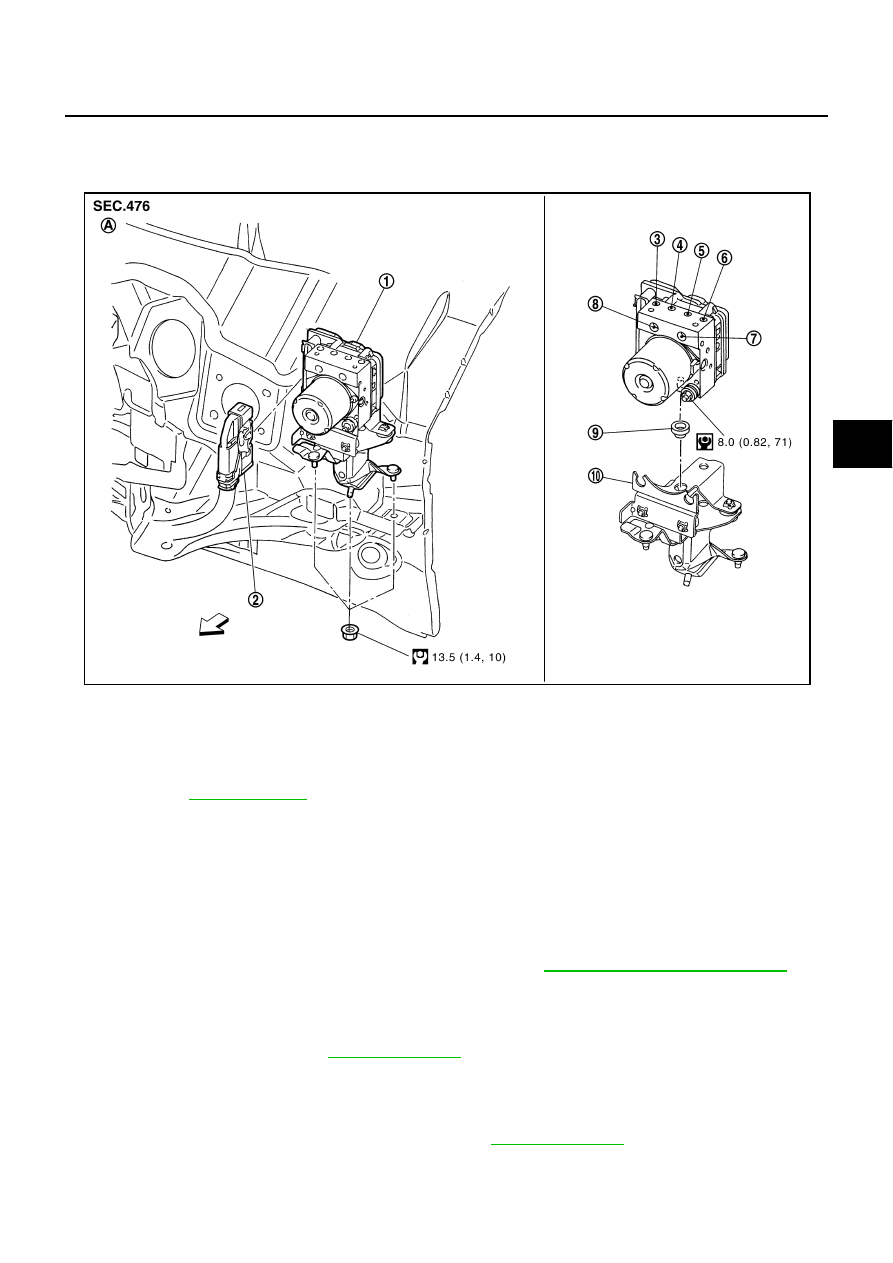
COMPONENT
CAUTION:
Be careful of the following.
●
Before servicing, disconnect the battery cable from negative terminal.
●
To remove brake tube, use a flare nut wrench to prevent flare nuts and brake tube from being dam-
aged. To install, use flare nut torque wrench.
●
Do not apply excessive impact to ABS actuator and electric unit (control unit), such as dropping it.
●
Do not remove and install actuator by holding harness.
●
After work is completed, bleed air from brake tube. Refer to
BR-10, "Bleeding Brake System"
●
After installing harness connector in the ABS actuator and electric unit (control unit), make sure
connector is securely locked.
REMOVAL
1.
Remove cowl top cover. Refer to
2.
Disconnect ABS actuator and electric unit (control unit) connector.
3.
Loosen brake tube flare nuts, then remove brake tubes from ABS actuator and electric unit (control unit).
4.
Remove tire.
5.
Remove fender protector (rear): (front LH side). Refer to
6.
Remove ABS actuator and electric unit (control unit) bracket mounting nut.
1.
ABS actuator and electric unit (con-
trol unit)
2.
Connector
3.
To front RH brake caliper
4.
To rear LH brake caliper
5.
To rear RH brake caliper
6.
To front LH brake caliper
7.
From master cylinder primary side
8.
From master cylinder secondary side 9.
Bushing
10.
Bracket
A.
Left side of dash panel
Refer to GI section
for symbol marks in the figure.
SFIA3018E
BRC-58
[VDC/TCS/ABS]
ACTUATOR AND ELECTRIC UNIT (ASSEMBLY)
7.
Remove ABS actuator and electric unit (control unit) from vehicle.
INSTALLATION
Installation is the reverse order of removal.
CAUTION:
When replacing ABS actuator and electric unit (control unit), make sure to adjust neutral position of
steering angle sensor. Refer to
BRC-6, "Adjustment of Steering Angle Sensor Neutral Position"
G-SENSOR
BRC-59
[VDC/TCS/ABS]
C
D
E
G
H
I
J
K
L
M
A
B
BRC
G-SENSOR
PFP:47930
Removal and Installation
NFS000RD
CAUTION:
●
Do not drop or strike yaw rate/side G sensor, because it has little endurance to impact.
●
Do not use power tool etc., because yaw rate/side G sensor is sensitive for the impact.
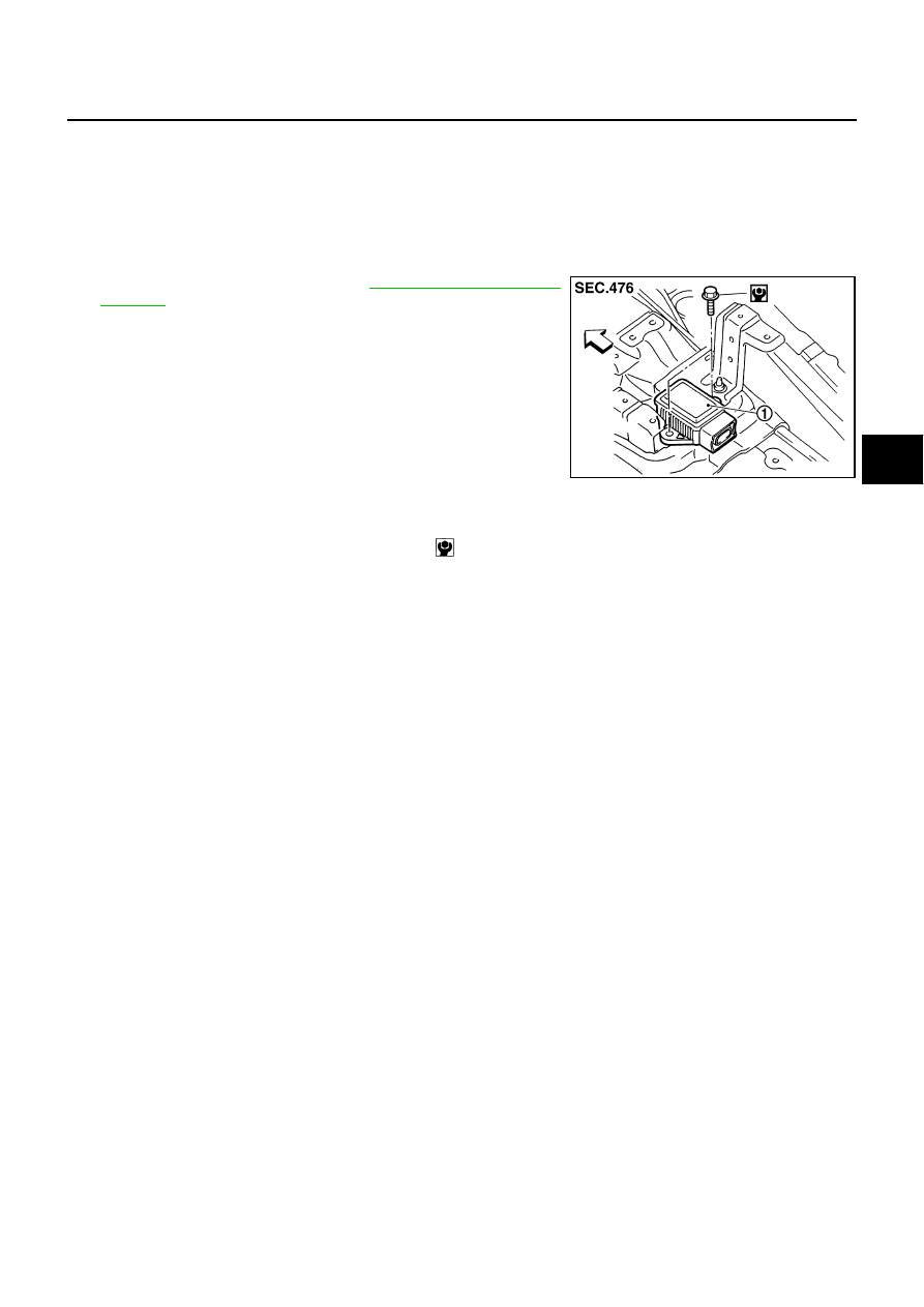
REMOVAL
1.
Remove center console. Refer to
2.
Disconnect yaw rate/side G sensor harness connector.
3.
Remove mounting bolts. Remove yaw rate/side G sensor (1).
INSTALLATION
Installation is the reverse order of removal.
SFIA2725J
Yaw rate/side G sensor mounting bolt
: 6.5 N·m (0.66 kg·m, 58 in-lb)

BRC-60
[VDC/TCS/ABS]
STEERING ANGLE SENSOR
STEERING ANGLE SENSOR
PFP:25554
Removal and Installation
NFS000RE
REMOVAL
1.
Remove spiral cable assembly. Refer to
2.
Remove steering angle sensor from spiral cable assembly.
INSTALLATION
Installation is the reverse order of removal.
CAUTION:
After work, make sure to adjust neutral position of steering angle sensor. Refer to
of Steering Angle Sensor Neutral Position"
SFIA1404E
Нет комментариевНе стесняйтесь поделиться с нами вашим ценным мнением.
Текст